Chapter 3, Motherboard information – Lanner FX-3210 User Manual
Page 21
16
Motherboard Information
Network Application Platforms
Chapter 3
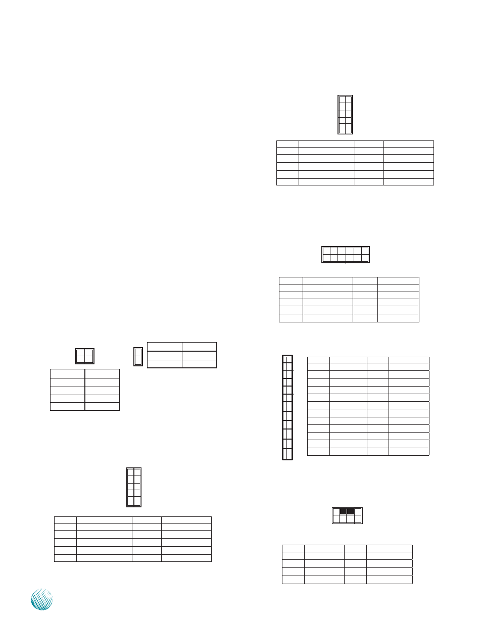
LED Signals on RJ45 port of the PCI-e Expansion Card : A
LED connector showing the LEDs of the RJ45 ports
LPC I/O bus (It can also be called Port 80) (LPC1): It is a
proprietary connector for connecting a checkpoint
device to output checkpoints throughout booting
and Power-On Self Test (POST) to indicate the task
the system is currently executing.
Front LCD Module Connector(J14): The 24-pin connector
is for connecting the front system panel.
Keyboard and Mouse Interface Cable Connectors (J10):
It is for connecting the PS/2 keyboard and mouse
interface cable.
Intel® RSTe OpROM utility for creating RAID
volume; to enter the RSTe OpROM, press Ctrl-I
during POST.
For operating systems other than Microsoft
3.
®
Windows Vista and Windows® 7, it is
required to pre-install the Intel Rapid Storage
Technology driver during the F6 installation of
Windows setup (“press F6 if you need to install
a third party SCSI or RAID driver....”).
Visit the Intel support page a
for more information and download links.
The Intel controller hubs are also supported
4.
by Linux. Beginning with Linux kernel
version 2.6.27, the mdadm utility 3.0
supports RAID 0, RAID 1, RAID 5, and RAID
10.
To use the RAID features in dmraid and mdadm,
you will need to set up the RAID volume using
the Intel® Matrix Storage Manager option ROM
(click CTRL + I when prompted during boot to
enter the option ROM user interface).
Power-switch Connector (SW1, CONN1): A tact as well as
the connector for switch button used for turning on or off
the power once the power supply is applied to the board.
USB Connector(USBA1&USBA2) : It is for connecting
the USB module cable. It complies with USB2.0 and
support up to 480 Mbps connection speed.
24
2
23
1
4
2
3
1
Pin No.
Pin name
1
GND
2
PS_ON#
1
2
Pin No.
Pin name
1
GND
2
GND
3
PS_ON#
4
PS_ON#
9
7
5
3
1
10
8
6
4
2
Pin No.
Function
Pin No.
Function
1
LED_SPEED_100
2
NC
3
LED_SPEED_1G
4
NC
5
LINK/ACT
6
NC
7
P3V3_DUAL
8
P3V3_DUAL
9
Ground
10
Ground
Pin No.
Function
Pin No.
Function
1
USB_VCC0
2
USB_VCC1
3
USBD0-
4
USBD1-
5
USBD0+
6
USBD1+
7
USB Port Ground
8
USB Port Ground
9
USB Port Ground
10
USB Port Ground
2
4
6
8
10
1
3
5
7
9
Pin No.
Function
Pin No.
Function
1
CLK_33M_P80
2
LPC_LAD1
3
RST_80DGPT_N
4
LPC_LAD0
5
LPC_FRAME_N
6
+3.3V
7
LPC_LAD3
8
Ground
9
LPC_LAD2
10
Ground
Pin No.
Function
Pin No.
Function
1
P5V
2
MSCLK
3
MSDATA
4
KEY
5
KBDATA
6
KEY
7
GND
8
KBCLK
1 3 5 7
2 4 6 8
PIN NO.
Function
Pin No.
Function
1
+5V
2
Ground
3
LSLIN#
4
VEE
5
LAFD#
6
LINIT#
7
FL_PD1
8
FL_PD0
9
FL_PD3
10
FL_PD2
11
FL_PD5
12
FL_PD4
13
FL_PD7
14
FL_PD6
15
LCD-
16
+5V
17
KPA1
18
KPA2
19
KPA3
20
KPA4
21
LCM_RST
22
CTR-GRN
23
CTR-YEW
24
HDLED_N
9 7 5 3 1
1 0 8 6 4 2