Chapter 3: motherboard information, Block diagram, Chapter 3 – Lanner FX-3210 User Manual
Page 15: Motherboard information
10
Motherboard Information
Network Application Platforms
Chapter 3
Chapter 3:
Motherboard Information
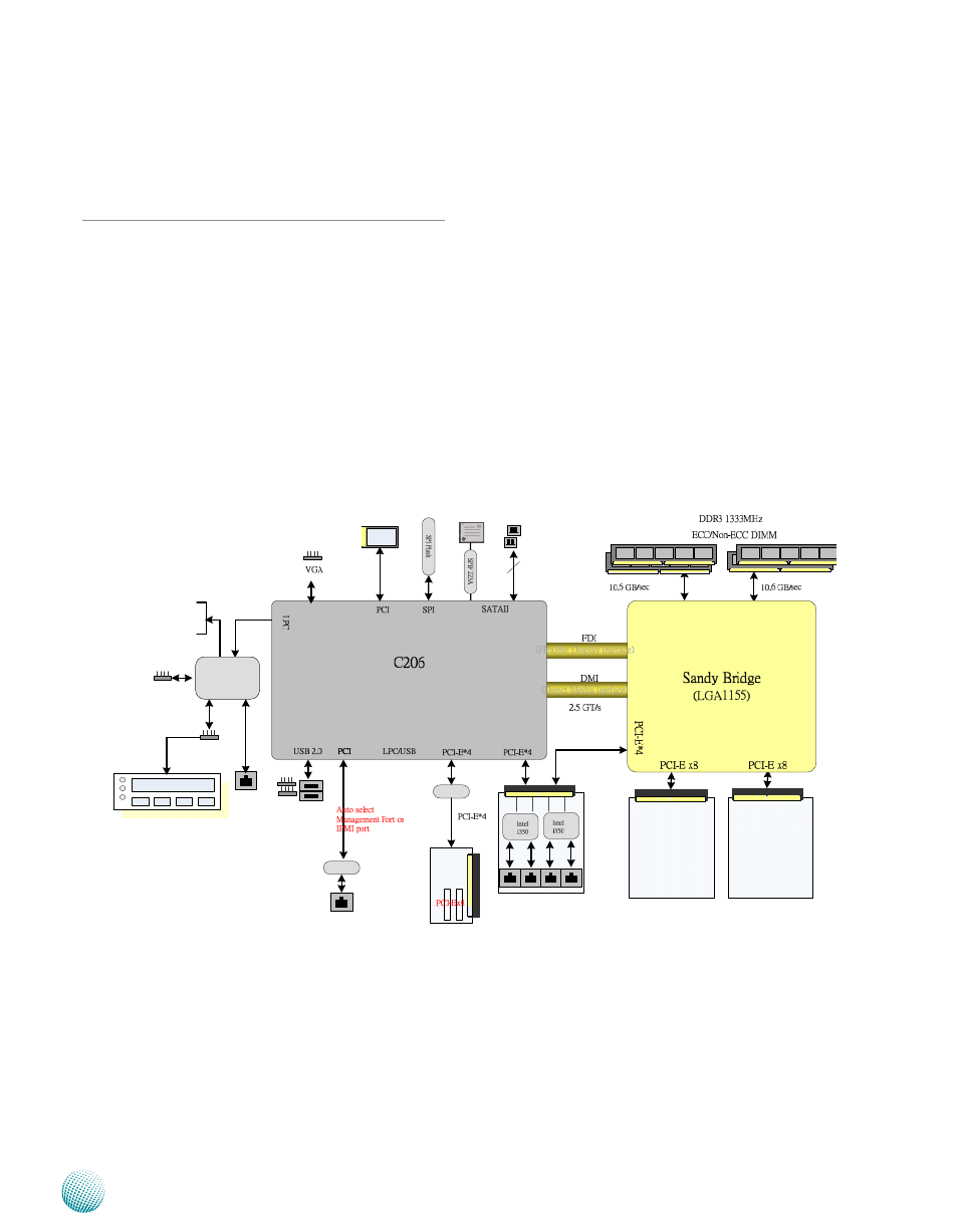
Block Diagram
The block diagram depicts the relationships among the
interfaces or modules on the motherboard. Please refer
to the following figure for your motherboard’s layout
design.
ˣ˖˜ˀ˘ʳ̋ˋʳ̆˿̂̇
˙̂̅ʳ˹̅̂́̇ʳ
ˡ˜˖ʳ̀̂˷̈˿˸
˖̂̀̃˴˶̇ʳ˙˿˴̆˻
ˇ̋ʳ
˦˔˧˔
˖̂̀ʳˣ̂̅̇̆
˟˖ˠ˂
˞˸̌ʳˣ˴˷
˞˕˂
ˠ̂̈̆˸
˚ˣ˜ˢ
˙˴́ʳˠ̂́˼̇̂̅
˅̋ʳ˨˦˕
˅̋ʳ˻˸˴˷˸̅
W83627DHG
˧˻˸̅̀˴˿ʳˠ̂́˼̇̂̅
˖̂̈˺˴̅ʳˣ̂˼́̇
ˣ˖˛
ˠ˼́˼ˀˣ˖˜
ˣ˖˜ˀ˘ʳ̋ˋʳ̆˿̂̇
˙̂̅ʳ˹̅̂́̇ʳ
ˡ˜˖ʳ̀̂˷̈˿˸
LCM Module
<
A
V
>
ˡ˜˖ʳ̆˿̂̇ʳ˄
ˡ˜˖ʳ̆˿̂̇ʳ˅
ˡ˜˖ʳ̆˿̂̇ʳˆ
˥˼̆˸̅
W83627DHG
MUX
Pericom
This manual is related to the following products: