Jumper settings, Chapter 3, Motherboard information – Lanner FX-3210 User Manual
Page 17
12
Motherboard Information
Network Application Platforms
Chapter 3
Jumper Settings
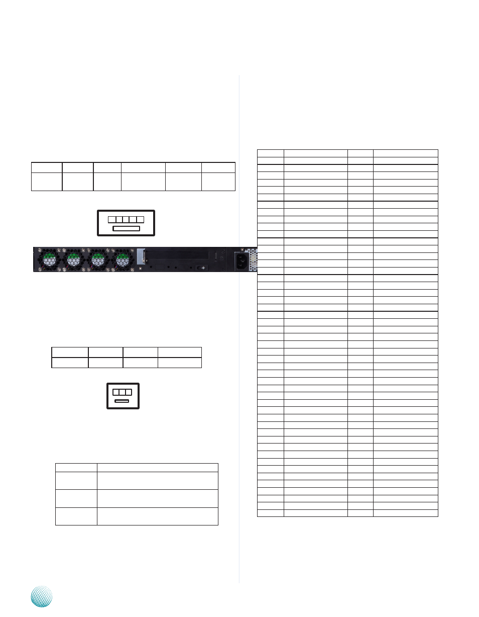
Fan Connectors(FAN1/FAN2/FAN3/FAN4): The 5-pin
connector is for connecting the CPU fans. It comes
with the smart fan feature by which the fans could
be monitored and turned on when the temperature
exceed the set threshold. Connect CPU fans to
FAN1and FAN3, and connect auxiliary fans to FAN2
and FAN4.
Fan Connectors(FAN5): The 3-pin connector is for
connecting the chassis fan.
PCIe Connectors(PCIEC4/PCIEC3/PCIEC1/PCIEC2): It is
for connecting the expansion cards which might be
an Ethernet card or a RAID card.
These PCIE sockets
offers a variation of PCIe lanes as listed below.
Jumper
Function
PCIEC1/2
PCI Express x8 SLOT having PCIe x8
mode
PCIEC3
PCI Express x8 SLOT having 2 PCIe x4
or 4 PCIe x1 mode
PCIEC4
PCI Express x8 golden finger having 1
PCIE x4 mode
Function
Ground
+12V
AUXFANIN1
PIN NO.
1
2
3
Pin No.
1
2
3
4
5
Function PWM
NC
FANIN
VFAN
GROUND
1 2 3 4 5
3 2 1
PCIEx8 Connector running at PCIEx8 mode
(PCIEC1,PCIEC2): to be connected to the front Ethernet
module. The jumper J31 can be used to select the
PCIe mode of these two connectors and jumper J32
can be used to select the order of the signal. Note
that with Ivy Bridge CPU, the PCIE also upgrades to
PCIe 3.0 standard (currently PCIe 2.0).
PIN NO.
FUNCTION
PIN NO.
FUNCTION
B1
+12V
A1
PRSNT1#
B2
+12V
A2
+12V
B3
+12V
A3
+12V
B4
GND
A4
GND
B5
SMCLK
A5
JTAG2
B6
SMDAT
A6
JTAG3
B7
GND
A7
JTAG4
B8
+3.3V
A8
JTAG5
B9
JTAG1
A9
+3.3V
B10
3.3VAUX
A10
+3.3V
B11
WAKE#
A11
PERST#
B12
BYPASS0 Mode
A12
GND
B13
GND
A13
REFCLKA+
B14
CPUPETP7/CPUPETP15
A14
REFCLKA-
B15
CPUPETN7/CPUPETN15
A15
GND
B16
GND
A16
CPUPERP7/CPUPERP15
B17
LANM0_LATCH_H
A17
CPUPERN7/CPUPERN15
B18
GND
A18
GND
B19
CPUPETP6/CPUPETP14
A19
BYPASS1 Mode
B20
CPUPETN6/CPUPETN14
A20
GND
B21
GND
A21
CPUPERP6/CPUPERP14
B22
GND
A22
CPUPERN6/CPUPERN14
B23
CPUPETP5/CPUPETP13
A23
GND
B24
CPUPETN5/CPUPETN13
A24
GND
B25
GND
A25
CPUPERP5/CPUPERP13
B26
GND
A26
CPUPERN5/CPUPERN13
B27
CPUPETP4/CPUPETP12
A27
GND
B28
CPUPETN4/CPUPETN12
A28
GND
B29
GND
A29
CPUPERP4/CPUPERP12
B30
REFCLK1A+
A30
CPUPERN4/CPUPERN12
B31
REFCLK1A-
A31
GND
B32
GND
A32
LANM1_LATCH_H
B33
CPUPETP3/CPUPETP11
A33
LANM1_LATCH_L
B34
CPUPETH3/CPUPETH11
A34
GND
B35
GND
A35
CPUPERP3/CPUPERP11
B36
GND
A36
CPUPERN3/CPUPERN11
B37
CPUPETP2/CPUPETP10
A37
GND
B38
CPUPETN2/CPUPETN10
A38
GND
B39
GND
A39
CPUPERP2/CPUPERP10
B40
GND
A40
CPUPERN2/CPUPERN10
B41
CPUPETP1/CPUPETP9
A41
GND
B42
CPUPETN1/CPUPETN9
A42
GND
B43
GND
A43
CPUPERP1/CPUPERP9
B44
GND
A44
CPUPERN1/CPUPERN9
B45
CPUPETP0/CPUPETP8
A45
GND
B46
CPUPETN0/CPUPETN8
A46
GND
B47
GND
A47
CPUPERP0/CPUPERP8
B48
LANM0_LATCH_L
A48
CPUPERN0/CPUPERN8
B49
GND
A49
GND
FAN4 FAN3 FAN2 FAN1
AUX Fan CPU Fan AUX Fan CPU Fan