Rear panel features, Chapter 1, Introduction – Lanner FW-7540 User Manual
Page 9
4
Introduction
Chapter 1
Network Application Platforms
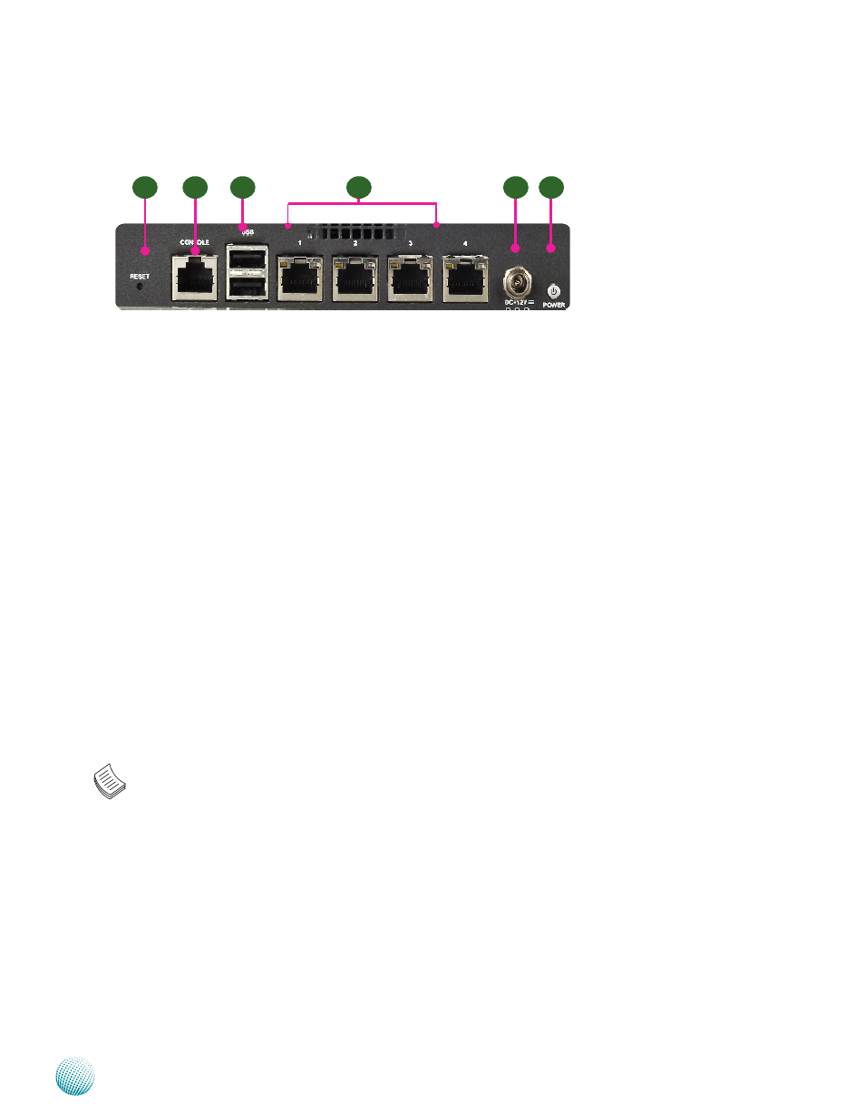
Rear Panel Features
R1 Reset Switch
Use a pointed object to press the reset button to reboot the system without turning off the power.
R2 Console Port
By using suitable rollover cable (also known as Cisco console cable), you can connect to a computer
terminal for diagnostic or configuration purpose. Default terminal configuration parameters: 9600
baud, 8 data bits, no parity, 1stop bit, and no flow control.
R3 Two USB 2.0 Ports
It connects to any USB devices, for example, a flash drive
R4 4 Gigabit LAN ports
Using suitable RJ-45 cable, you can connect FW-7540 System to a computer, or to any other piece
of equipment that has an Ethernet connection; for example, a hub or a switch. Moreover,2 pair
(LAN1-LAN2 and LAN3-LAN4) can be configured as LAN Bypass when failure events occur. LAN 1
(provided by Intel 82574L) is also capable of the Preboot Execution Environment (PXE) function.
R5 DC-in 12V Jack
The system requires a 60W/12V power adapter with lock.
R6 Power-on Switch
It is a switch to turn on or off the power.
Note:
The availability of LAN Bypass varies depending on the models.
1.
Both PXE and Lan Bypass functionalities can be enabled or disabled in the BIOS
2.
menu. Lanner provides three methods for enabling the LAN Bypass function:
When the system powers off, it can be forced to enable the LAN Bypass function through
•
the BIOS settings.( See BIOS Settings)
When the system is running, the LAN Bypass function can be dynamically enabled or
•
disabled through GPIO (General Purpose Input and Output) by programming. Furthermore,
with the use of watchdog timer, the LAN bypass can be automatically enabled when system
anomalies is detected.
R1
R2
R5
R3
R4
R6