Jumper settings, Chapter 3, Motherboard information – Lanner FW-7540 User Manual
Page 17
12
Motherboard Information
Chapter 3
Network Application Platforms
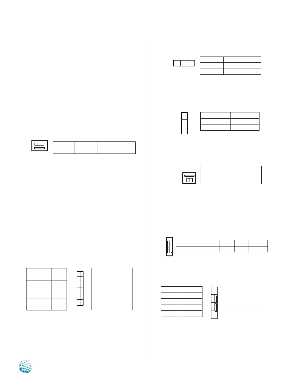
Clear CMOS Jumper (JP1): It is for clearing the
CMOS memory and system setup parameters by erasing
the data stored in the CMOS RAM such as the system
passwords.
ATX Power Button Connector (CONN2): The
power button has a 2-pin connector; the pin definition is
as the following:
CompactFlash Connector (CN1): It is for connecting a
Compact Flash card to be served as your system's storage.
The socket is CF type II and can fit into both bype I and
type II cards.
Serial-ATA Power Connector (J5): It is used for
connectig the SATA power cord.
Keyboard and Mouse Connector (J8): It is for
connecting the PS/2 keyboard and mouse interface
cable.
Jumper Settings
DIMM Socket (DIMM1): The single memory
slot (240 pin) is for connecting the DIMM (Dual In-line
Memory Module) memory. The system requires a Single
Chanel non-ECC DDR2 667 MHz memory and suports up
to 4 GB in maximum.
FAN Connector (FAN1, FAN2): The 3-pin connector
is for connecting the system fan. The BIOS will list the
CPU and system fans’ monitored temperature and speed
under the menu of Hardware Health Configuration. You
could also configure the target temperature to adjust the
fan speed automatically. Please connect CPU Fan to Fan2
and System Fan to Fan1.
VGA Interface Connector (J4): It is for connecting
the VGA interface cable (2x6 to female DB15). The VGA is
provided by the integrated GPU which implements Intel®
Graphics Media Accelerator 3150 which supports the
following features:
Contains a refresh of the third generation graphics
•
core.
Intel
•
® Dynamic Video Memory Technology support
4.0
Directx* 9 compliant Pixel Shader* v2.0
•
500MHz render clock frequency
•
Analog RGB displayoutput resolution up to 2048 *
•
1536 @ 60Hz
Intel
•
® Clear Video Technology including MPEG2
Hardware Acceleration and ProcAmp
Hardware or Software Reset Jumper(JP2): The
jumper can be adjusted to be in either hardware or
software reset mode when the reset switch is pressed. The
hardware reset will reboot the system without turning
off the power. The software reset can be programmed to
reset a software to its default setting.
Function
Ground +12V Fan Status
PIN NO.
1
2
3
Pin No.
Pin name
1
GND
2
ICH_PWRBTN1_N
PIN NO.
1
2
3
4
Function VCC(12V) GND GND VCC(5V)
4
3
2
1
Pin No. Function
1
VCC
3
MSDATA
5
KBDATA
7
GND
Pin No. Function
2
MSCLK
4
KEY
6
KEY
8
KBCLK
1
3
5
7
2
4
6
8
3 2 1
Pin No. Function
11
DD_DATA
9
V-SYNC
7
H-SYNC
5
Blue
3
Green
1
Red
12
10
8
6
4
2
11
9
7
5
3
1
Function Pin No.
DD_CLK
12
GND
10
GND
8
GND
6
GND
4
CRT ON
2
Pin No.
Function
1-2
Software Reset
2-3
Hardware Reset
3 2 1
Pin No.
Function
1-2 (Default)
Normal
2-3
Clear CMOS
1
2
3
2 1