Chapter 3, Motherboard information – Lanner FW-7540 User Manual
Page 19
14
Motherboard Information
Chapter 3
Network Application Platforms
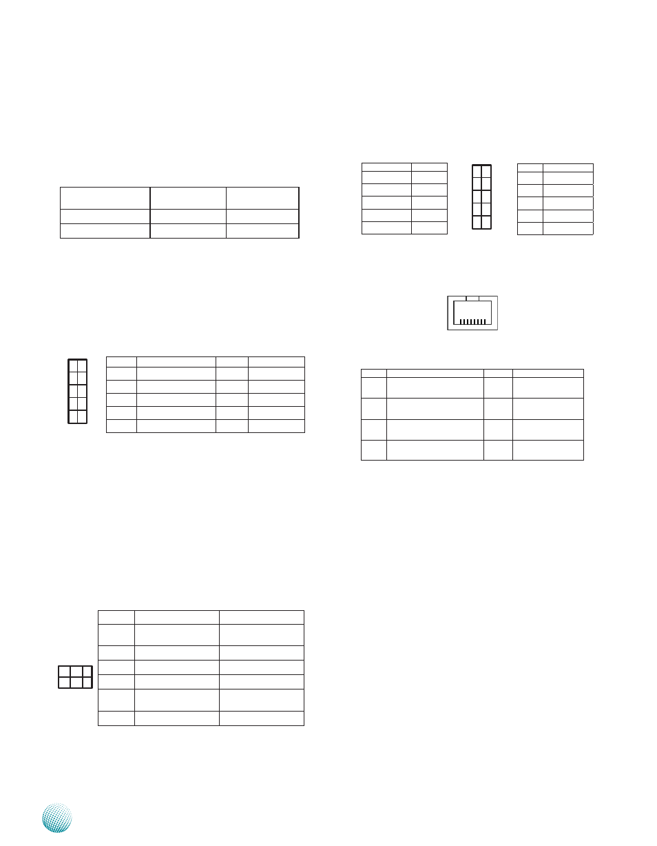
USB Module Connector (J6): It is for connecting
the USB module cable. It complies with USB2.0 and is
capable of low-speed, full-speed, and high-speed which
can support up to 480 Mbps connection speed.
Serial Interface (LAN1)
CompactFlash Master/Slave Selection (JP3):
The CF card interfaces to the system by using the ATA
controller. Select CompactFlash card storage device as
master or slave when there are other ATA compatible
devices connected to the system. However, the CF card is
the only ATA compatible device that exists in the system.
LPC I/O bus (Port 80 output for Debug Card)
(LPC1): It is an Intel proprietary connector for connecting
a checkpoint device to output checkpoints throughout
bootblock and Power-On Self Test (POST) to indicate the
task the system is currently running.
WAN Status LED (J9): If a wireless module is
connected to the system, these headers can be used to
connect to LED indicators to show the connection status
of the wireless network. The wireless module can be
connected by using the Mini PCI-E socket(MPCIE1) along
for Wireless LAN or both Mini PCI-E socket and the SIM
card tray for Wireless WAN connectivity.
5 3 1
6 4 2
Pin No.
Function
Description
1
LED1_WWAN_N
Wireless Wide
Area Network
2
VCC
3
LED1_WLAN_N
Wireless LAN
4
VCC
5
LED1_WPAN_N Wireless Personal
Area Network
6
VCC
1
3
5
7
9
2
4
6
8
10
Function
Pin No.
VCC
1
USBP_N2
3
USBP_P2
5
Ground
7
Ground
9
Pin No.
Function
2
VCC
4
USBP_N3
6
USBP_P3
8
Ground
10
Key
C o m p a c t F l a s h
Card.
ATA Disk Chip
Jumper
Master
Slave
1-2 (Default)
Slave
Master
2-3
Pin No.
Function
Pin NO.
Function
1
PLTRST_P80
6
VCC3P3
2
LPC_LAD1
7
LPC_AD3
3
PLTRST_P80_N
8
GND
4
LPC_AD0
9
LPC_AD2
5
LPC_FRAME_N
10
GND
1
3
5
7
9
2
4
6
8
10
Pin No.
Function
Pin No.
Function
1
Request To Send
(RTS)
5
Signal Ground
2
Data Terminal Ready
(DTR)
6
Received Data
(RxD)
3
Transmitted Data
(TxD)
7
Data Set Ready
(DSR)
4
Signal Ground
8
Clear To Send
(CTS)
8 1