Chapter 3, Motherboard information – Lanner FW-7540 User Manual
Page 18
13
Motherboard Information
Chapter 3
Network Application Platforms
Mini PCI-E Socket (MPCIE1): It is for connecting WiFi
module to serve Wireless LAN connections or connecting
Wireless 3G module for mobile Internet connections. The
socket supports both PCI-E and USB signal.
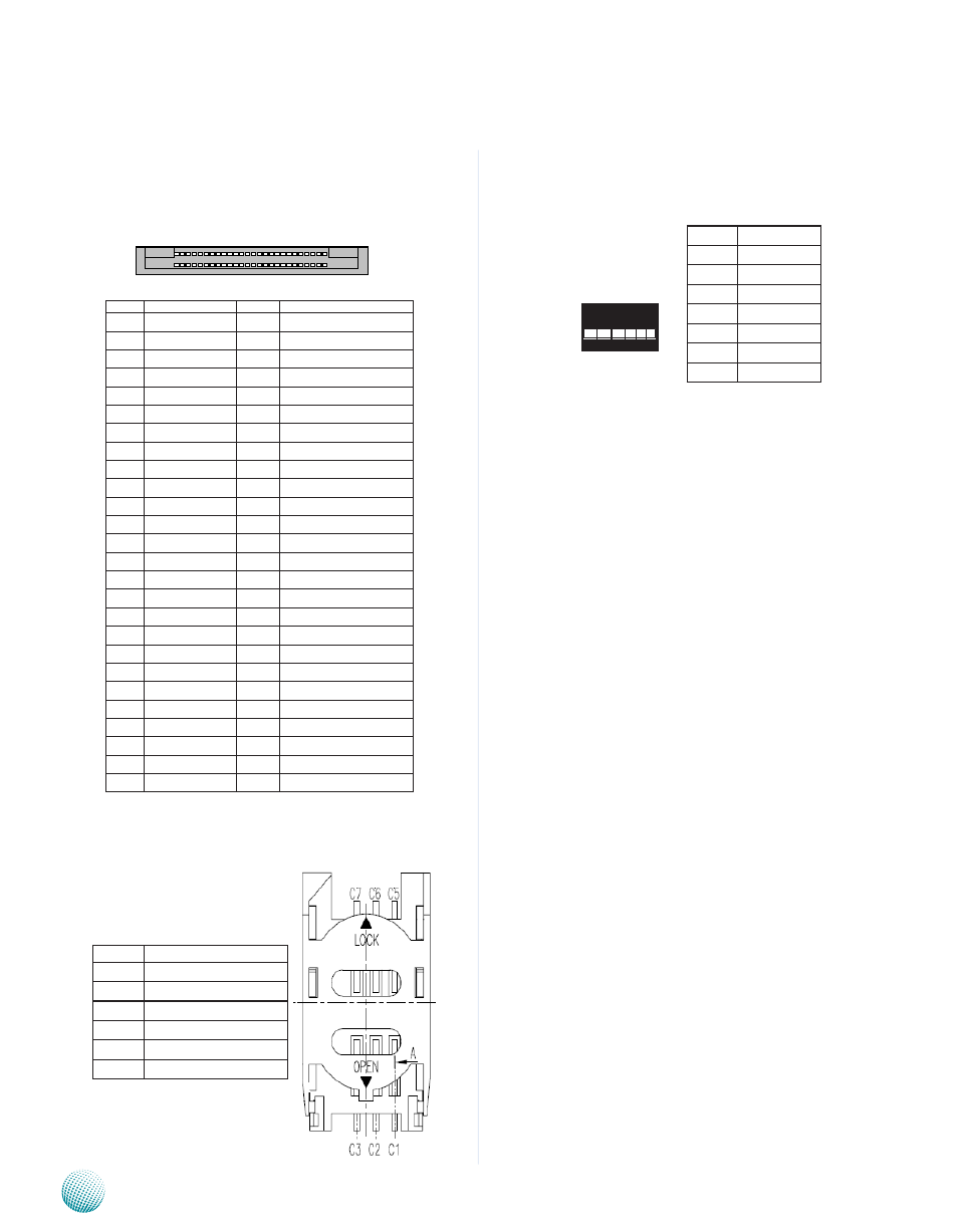
SIM Card Tray (CON1): It is for connecting SIM card
for mobile Internet connection.
SATA 1 and 2 Connectors(J1, J2): It is for
connecting a 2.5’’ SATA harddisk to be served as your
system’s storage. It supports data transfer rates at up to
3.0 Gb/s (300 MB/s).
The SATA controller contains two modes of
operation—a legacy mode using I/O space, and an
AHCI mode using memory space. Software that uses
legacy mode will not have AHCI capabilities. (Refer
to
ATA/IDE Configuration
on Chapter 4 Bios Settings).
The AHCI ( Advanced Host Controller Interface) is a
programming interface which defines transactions
between the SATA controller and software and
enables advanced performance and usability with
SATA. Platforms supporting AHCI may take advantage
of performance features such as no master/slave
designation for SATA devices—each device is treated
as a master—and hardware assisted native command
queuing. AHCI also provides usability enhancements
such as Hot-Plug.
To enable the AHCI mode, you will need to:
Select the AHCI option for SATA configuration in
1.
the BIOS menu.
PreInstall the AHCI driver when installing the
2.
Windows (F6 during Windows® setup). For
drivers, visit the Intel download center at: http://
downloadcenter.intel.com
Pin No. Function
1
Ground
2
TX+
3
TX-
4
Ground
5
RX-
6
RX+
7
Grdoun
1 2 3 4 5 6 7
52 2
51 1
Pin NO..
Function
Pin NO.
Function
1
WAKE#
27
GND
2
VCC3
28
1.5V
3
RSV1
29
GND
4
GND
30
SMB_CLK
5
RSV2
31
NC(PETn)
6
1.5V
32
SMB_DATA
7
CLKREQ#
33
NC(PETp)
8
UIM_PWR
34
GND
9
GND
35
GND
10
UIM_DATA
36
USB_D-
11 NC(REFCLK-)
37
RSV5
12
UIM_CLK
38
USB_D+
13 NC(REFCLK+) 39
RSV6
14
UIM_RST
40
GND
15
GND
41
RSV7
16
UIM_VPP
42
LED_WWAN#
17
RSV3
43
RSV8
18
GND
44
NC(LED_WLAN#)
19
RSV4
45
RSV9
20 W_DISABLE# 46
NC(LED_WPAN#)
21
GND
47
RSV10
22
PERST
48
1.5V
23
NC(PERn)
49
RSV11
24
3.3VAUX
50
GND
25
NC(PERp)
51
RSV12
26
GND
52
VCC3
Pin No.
Function
C1
VCC
C2
MSM_USIM_RESET
C3
MSM_USIM_CLK
C5
GND
C6
MSM_USIM_VPP
C7
MSM_USIM_DATA