Chapter 2, Hardware setup – Lanner FW-7540 User Manual
Page 14
9
Hardware Setup
Chapter 2
Network Application Platforms
Connecting Powers
Follow theses procedures to power up the FW-7540:
Connect one end of the AC power to the DC jack of the
1.
FW-7540 first.
Connect the other end of the power cord to the DC
2.
power adapter socket.
Lastly, connect the power cord to an electrical outlet.
3.
CAUTION: Leave space around your power
adapter. Do not use this device in a location where
airflow around the power adapter or computer
is not sufficient. Always disconnect the power
adapter before opening the computer to perform
procedures such as installing memory or removing
the hard disk.
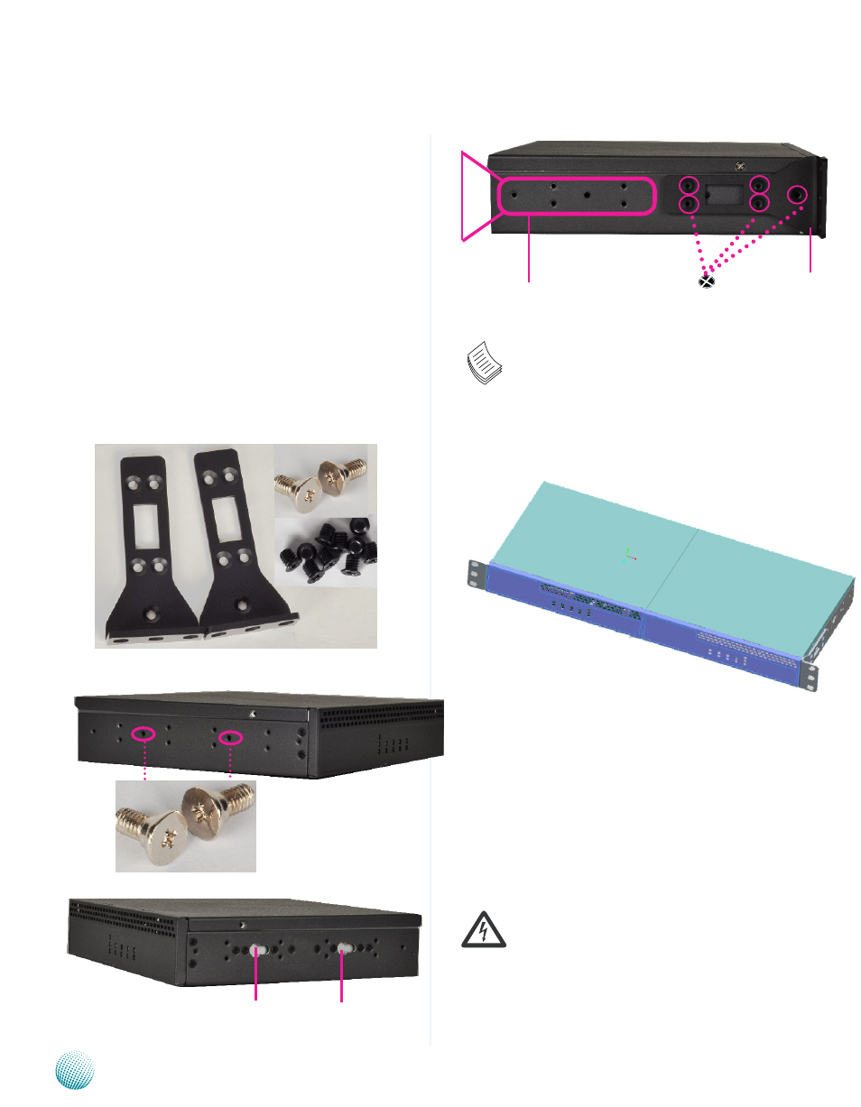
Mounting Two systems to the Rack
To mount two FW-7540 systems onto the rack, use the
mounting kit with the screw pack. Follow the following
procedures as a guideline:
Attaching two screws having a washer under the head
1.
to the inner side of the system’s chassis as shown in
the picture below.
Align the screws of one system with the mounting
2.
slots of the other system and mount the two systems
side by side by clipping them together
Make sure that the attachment between the two
3.
systems is secure and the mounting screws is locked
in place.
Use the screws provided to fix the short ear-bracket to
4.
the left and right sides of the system as shown in the
picture.
Mounting
slots
Mounting
slots
Two system mounting kit
Short ear-
bracket
Installing mounting screws
for clipping the other system
Mounting holes for clipping
two systems together
Installing the ear-bracket to the
rear side as an alternative
Rack mounting
Note:
The short-ear bracket could also be mounted at
the rear side of the system as shown in the above
figure. Thus, the rear panel of the system could
be mounted in the front of the rack mounting
equipment.
Mounting short-ear bracket