2 overtravel, Caution, 1) signal setting – Yaskawa Sigma-5 User Manual: Design and Maintenance - Rotary Motors - MECHATROLINK-II Communications Reference User Manual
Page 91: 2) overtravel function setting, 46 and 64
4 Operation
4.3.2 Overtravel
4-6
4.3.2 Overtravel
The overtravel limit function forces movable machine parts to stop if they exceed the allowable range of
motion and turn ON a limit switch.
For rotating application such as disc table and conveyor, overtravel function is not necessary. In such a case,
no wiring for overtravel input signals is required.
(1) Signal Setting
Rotation in the opposite direction is possible during overtravel by inputting the reference.
(2) Overtravel Function Setting
Parameters Pn50A and Pn50B can be set to enable or disable the overtravel function.
If the overtravel function is not used, no wiring for overtravel input signals will be required.
A parameter can be used to re-allocate input connector number for the P-OT and N-OT signals. Refer to 3.3.1
Input Signal Allocations for details.
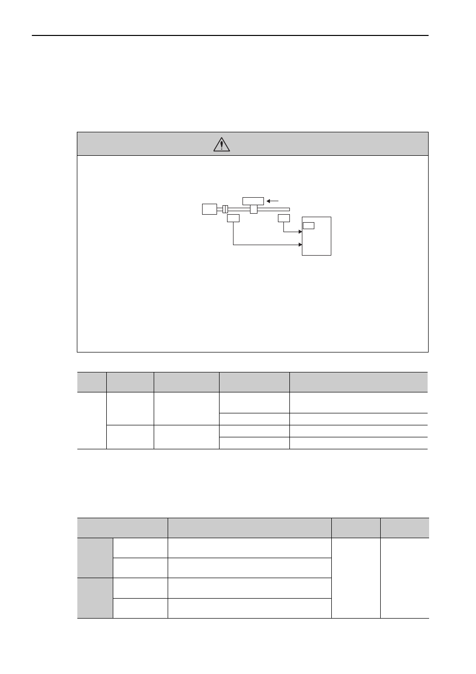
CAUTION
• Installing limit switches
For machines that move using linear motion, connect limit switches to P-OT and N-OT of CN1 as shown below to
prevent machine damage. To prevent a contact fault or disconnection from causing accidents, make sure that the limit
switches are normally closed.
• Axes to which external force is applied in overtravel
Vertical axes:
Occurrence of overtravel may cause a workpiece to fall, because the /BK signal is on, that is when the brake is
released. Set the parameter (Pn001 = n.
1 ) to bring the servomotor to zero clamp state after stopping to prevent
a workpiece from falling.
Other axes to which external force is applied:
Overtravel will bring about a baseblock state after the servomotor stops, which may cause the servomotor to be
pushed back by the load’s external force. To prevent this, set the parameter (Pn001 = n.
1 ) to bring the servo-
motor to zero clamp state after stopping.
For details on how to set the parameter, refer to (3) Servomotor Stopping Method When Overtravel is Used.
8
CN1
7
P-OT
N-OT
Limit
switch
SERVOPACK
Limit
switch
Forward direction
Servomotor
46 and 64
Type
Name
Connector
Pin Number
Setting
Meaning
Input
P-OT
CN1-7
ON
Forward run allowed.
Normal operation status.
OFF
Forward run prohibited. Forward overtravel.
N-OT
CN1-8
ON
Reverse run allowed. Normal operation status.
OFF
Reverse run prohibited. Reverse overtravel.
Parameter
Meaning
When
Enabled
Classification
Pn50A
n.1
[Factory setting]
Inputs the Forward Run Prohibited (P-OT) signal from
CN1-7.
After restart
Setup
n.8
Disables the Forward Run Prohibited (P-OT) signal.
Allows constant forward rotation.
Pn50B
n.
2 [Fac-
tory setting]
Inputs the Reverse Run Prohibited (N-OT) signal from
CN1-8.
n.
8
Disables the Reverse Run Prohibited (N-OT) signal.
Allows constant reverse rotation.