3 example of i/o signal connections, 46and64 – Yaskawa Sigma-5 User Manual: Design and Maintenance - Rotary Motors - MECHATROLINK-II Communications Reference User Manual
Page 69
3 Wiring and Connection
3.2.3 Example of I/O Signal Connections
3-20
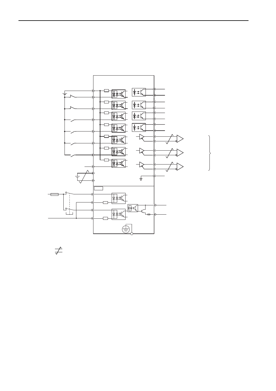
3.2.3 Example of I/O Signal Connections
The following diagram shows a typical connection example.
∗1.
represents twisted-pair wires.
∗2. Connect when using an absolute encoder. When the encoder cable with the battery case is connected, do not connect
a backup battery.
∗3. The 24-VDC power supply is not included. Use a 24-VDC power supply with double insulation or reinforced insula-
tion.
∗4. When using the safety function, a safety function device must be connected and the wiring that is necessary to acti-
vate the safety function must be done to turn ON the servomotor power. When not using the safety function, use the
SERVOPACK with the JZSP-CVH05-E Plug (provided as an accessory) inserted into the CN8.
∗5. Always use line receivers to receive the output signals.
Note: The functions allocated to the input signals /DEC, P-OT, N-OT, /EXT1, /EXT2, and /EXT3 and the output signals
/SO1, /SO2, and /SO3 can be changed by using the parameters. Refer to 3.3.1 Input Signal Allocations and 3.3.2
Output Signal Allocations.
SO1+ / BK+
SO1- / BK-
/SO2+
/SO2-
/SO3+
ALM+
ALM-
1
2
23
24
3
4
+24VIN
+24V
3.3 k
Ω
6
8
10
9
11
12
/SI0
P-OT
N-OT
/DEC
/EXT1
/EXT2
/EXT3
BAT+
BAT-
13
14
15
7
/SO3-
SERVOPACK
25
26
16
SG
∗1.
∗2.
∗3.
PBO
PCO
/PBO
PAO
/PAO
/PCO
21
17
18
19
20
22
EDM1+
EDM1-
FG
/HWBB1+
/HWBB1-
/HWBB2+
/HWBB2-
24V
0V
Safety function device∗4
ޓޓޓޓޓޓ
CN8
6
3
4
5
8
7
Encoder output
pulse phase A
Encoder output
pulse phase B
Encoder output
pulse phase C
Applicable line receiver:
SN75ALS175 or
MC3486 manufactured
by Texas Instruments or
the equivalent
Photocoupler output
Max. operating voltage: 30 VDC
Max. output current: 50 mA DC
Connect shield to
connector shell.
Connector
shell
SERVOPACK
Switch
Fuse
General-
purpose
Servo alarm output
(OFF for an alarm)
Brake
(Brake released when ON)
Reverse run prohibited
(Prohibited when OFF)
Forward run prohibited
(Prohibited when OFF)
External latch signal 1
(Latched when ON)
External latch signal 2
(Latched when ON)
External latch signal 3
(Latched when ON)
Homing deceleration
switch
(Decelerated when ON)
Control power supply
for sequence signal
Backup battery
(2.8 to 4.5 V)
∗5
∗5
∗5
46and64