Rotation – Yaskawa Sigma-5 User Manual: Design and Maintenance - Rotary Motors - MECHATROLINK-II Communications Reference User Manual
Page 293
8.3 Parameter Settings for Fully-closed Loop Control
8-19
8
Fu
lly-close
d L
oop
Co
ntro
l
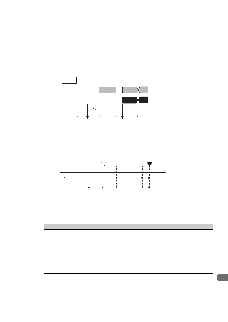
(2) Absolute Data Transmission Sequence and Contents
1. Send the Turn Encoder Power Supply ON (SENS_ON) command from the host controller.
2. After 100 ms, set the system to serial data reception-waiting-state. Clear the incremental pulse up/down
counter to zero.
3. Receive eight characters of serial data.
4. The system enters a normal incremental operation state about 400 ms after the last serial data is received.
Serial data:
The current position pulses divided by Pn281 are output in serial data.
One serial data is a value equivalent to 1048576 pulses.
Initial incremental pulses:
The current position pulses divided by Pn281 are output in pulses. The number of output pulses is between 0
to 1048576, and the output speed is approximately 1.48 µs per pulse.
Final absolute data P
M
is calculated by following formula.
P
E
=M
O
× R+P
O
P
M
=P
E
–M
S
×R–P
S
Note: If host controller receives the data from the external absolute encoder, do not perform counter reset using the output
of PCO signal.
SENS_ON
(Turn Encoder
Power Supply ON)
PAO
PBO
Incremental pulses
Incremental pulses
Undefined
Undefined
(Phase A)
(Phase A)
(Phase B)
(Phase B)
Serial data
400 ms max.
50 ms
1 to 3 ms
About 15 ms
90 ms typ.
60 ms min.
Initial
incremental
pulses
Initial
incremental
pulses
46
0 1 2 3
3 (Mo)
2
0 1
(M
S
)
P
E
P
M
P
S
M
S
× R
M
o
× R
P
O
Coordinate
value
Values of
Mo and Ms
Reference position (at setup)
Current position
Rotation
Signal
Meaning
P
E
Current position of external encoder
M
O
Serial data of current position
P
O
Number of initial incremental pulses of current position
M
S
Serial data of reference position
P
S
Number of initial incremental pulses of reference position
P
M
Current value required for the user’s system
R
1048576