2 grounding the network, 1 grounding methods, 260if communications – Yaskawa 260IF DeviceNet System User Manual
Page 82: Using multiple power supplies
7.2 Grounding the Network
7-9
7
7.2 Grounding the Network
This section explains how to ground the network.
7.2.1 Grounding Methods
260IF Communications
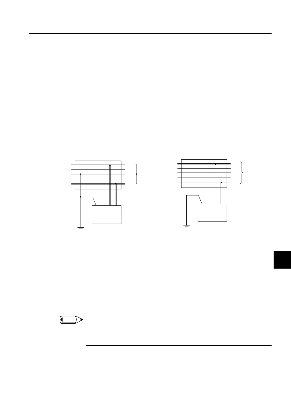
To avoid creating a ground loop, ground the network at one point only for 260IF Module
communications. Position the ground as close to the center of the network as possible.
As shown in the following diagram, connect the cable shield wire to the ground terminal
(FG) on the power supply. Ground to a resistance of 100
Ω or less.
Using Multiple Power Supplies
When using multiple power supplies for communications, connect the shield wire to the
power supply ground near the center of the network only. Do not connect the shield wire at
any other power supplies.
Use Power Supply Taps when connecting multiple communications power supplies to a net-
work.
Power supplies are not counted as nodes.
1 Always ground to a resistance of 100
Ω or less.
2 Ground the power supply separately from the servodrives and inverters.
3 Do not connect the shield wire to multiple points on the network. Connect it to one point only.
Cable Grounded at Power Supply (one place only)
Cable Not Grounded at Power Supply
V+
CAN H
CAN L
V-
V+
V-
FG
Communication
cable
T-branch or Power Supply Tap
Shield
Communications
power supply
Ground to a resistance
of 100
Ω or less
V+
CAN H
CAN L
V-
V+
V-
FG
Power Supply Tap
Shield
Communications
power supply
Communication
cable
Ground to a resistance of 100
Ω or less.
INFO