I/o allocations – Yaskawa 260IF DeviceNet System User Manual
Page 45
System Startup and Setup
4.3.2 Setting Methods
4-12
4
I/O Allocations
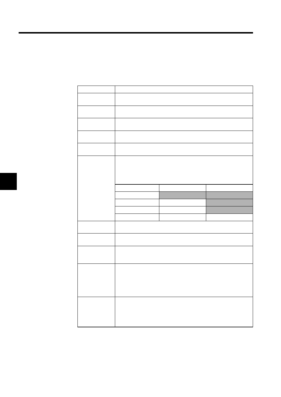
The asterisks (**) displayed on the left in the I/O allocations table indicate the 260IF Mod-
ule allocations in the Module Configuration Window.
Setting
Contents
Master/Slave
Sets the operating mode (DeviceNet Master/Slave) for the 260IF Module. Set
the same value as that set on SW1 (X1) on the 260IF Module.
MAC ID
The DeviceNet MAC ID (DeviceNet address) for the 260IF Module. Set the
same value as that set on SW2 and SW3 on the 260IF Module.
MAC ID column
This is the MAC ID (DeviceNet address) for I/O allocations. It is automatically
allocated in order starting from 00.
D
Sets whether or not the Controller CPU will exchange I/O data with the 260IF
Module. Turn ON (check) this setting if the data is not to be exchanged.
INPUT
Sets the leading address of the input area (input register IWxxxx) for the 260IF
Module input data . Specify a hexadecimal address.
BSIZE
Sets the size of the output area for the device (input register IWxxxx) in num-
ber of bytes. Specify a number of bytes between 1 and 256 (decimal) for each
Slave.
For example, if the setting is 3 bytes from IW1100 and one byte from IW1102,
the register area shown in the following diagram will be allocated.
Register No.
F……8
7……0
IW1100H
IW1101H
IW1102H
IW1103H
D
Sets whether or not the Controller CPU will exchange I/O data with the 260IF
Module. Turn ON (check) this setting if the data is not to be exchanged.
OUTPUT
Sets the leading address of the output area (output register OWxxxx) for the
260IF Module output data. Specify a hexadecimal address.
BSIZE
Sets the size of the output area for the device (output register OWxxxx) in
number of bytes. Specify a number of bytes between 1 and 256 (decimal) for
each Slave. The byte order is little-endian, the same as for input registers.
SCAN
The data exchange cycle (SCAN) is when the Controller CPU exchanges I/O
data with the 260IF Module. The Controller CPU data exchange cycle is asyn-
chronous with the I/O communications. When set to "High," the Controller
CPU will exchange I/O data during the high-speed scan of the CPU. When set
to "Low," the Controller CPU will exchange I/O data during the low-speed
scan of the CPU.
TYPE
Sets the I/O communication type (TYPE) to either "Polled" or "Strobed."
Polled means settings can be made for any DeviceNet device.
Strobed means settings can be made for inputs only and for DeviceNet Slaves 8
bytes or less in size.
Refer to DeviceNet specifications for details on Polled and Strobed settings.