Calculation from the formula, Formula – Yaskawa 260IF DeviceNet System User Manual
Page 79
Wiring
7.1.3 Methods for Deciding the Power Supply Positioning
7-6
7
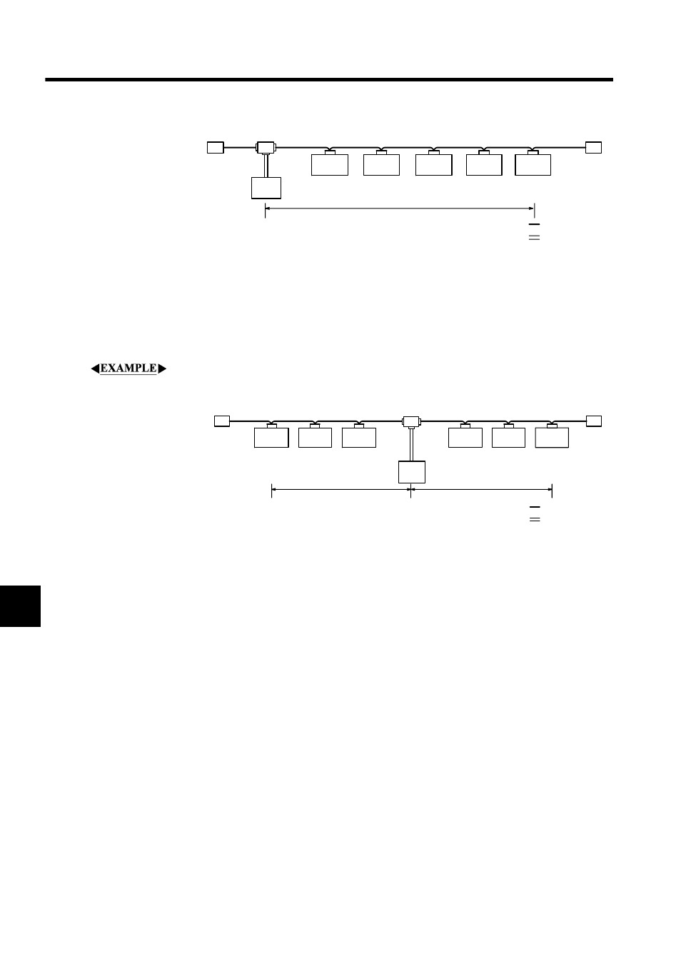
• Total length of power supply = 200 m
• Total current consumption = 0.2 A
+ 0.1 A + 0.05 A + 0.2 A + 0.15 A = 0.7 A
• Max. current according to the graph = 1.53 A
The total current consumption
< maximum current. Therefore, communications power can
be supplied to all nodes.
Example 2: Power Supply Positioned in the Middle of the Network
The following diagram shows the layout when the power supply is positioned in the middle
of the network and a thick cable with a total length of 200 m is used.
• Total power supply length on the left side = Total power supply length on the right
side=120 m
• Total current consumption on the left side = 0.2 A
+ 0.3 A + 0.1 A = 0.6 A
• Total current consumption on the right side = 0.25 A
+ 0.15 A + 0.1 A = 0.5 A
• Max. current on the left side according to the graph = Approx. 2.5 A
• Max. current on the right side according to the graph = Approx. 2.5 A
The total current consumption on the left side
< maximum current on the left side and the
total current consumption on the right side
< maximum current on the right side. Therefore,
communications power can be supplied to all nodes.
Calculation from the Formula
If the conditions cannot be met with simple calculation from the graph method, use the more
detailed method of calculation from the formula.
Formula
1. For separate communications and internal circuit power supplies
Terminating
resistance
Trunk line
Terminating
resistance
Communications
power supply
Node
Node
Node
Node
Node
0.2 A
0.1 A
0.05 A
0.2 A
0.15 A
200 m
: Trunk line
: Power supply
cable
Terminating
resistance
Trunk line
Trunk line
Node
Node
Node
Node
Node
Node
Terminating
resistance
0.2 A
0.3 A
0.1 A
0.25 A
0.15 A
0.1 A
Communications
power supply
120 m
120 m
: Power supply
cable
:Trunk line