Yaskawa 260IF DeviceNet System User Manual
Page 77
Wiring
7.1.3 Methods for Deciding the Power Supply Positioning
7-4
7
or the simple calculation from the graph.
Make sure that each drop line meets the conditional expression for the length and current
capacity of the drop line, as outlined in item 6 of 7.1.1 Basic Precautions.
1 Have separate communications and internal circuit power supplies whenever possible.
2 If the same power supply must be used for both communications and internal circuit power supplies,
the method of simple calculation from the graph cannot be used. Always use the calculation from the
formula method.
Simple Calculation from the Graph
Simple Calculation
The voltage in the communications power supply section of each node must be 11 VDC or
higher. The communications will become unstable if the voltage is lower than 11 VDC.
Voltage drop will occur when current flows through the transmission cable. This voltage
drop will increase the longer the transmission cable and the larger the current.
The following table shows the maximum current for each cable to allow sufficient voltage to
be supplied to the communications power supply section even if voltage drop occurs.
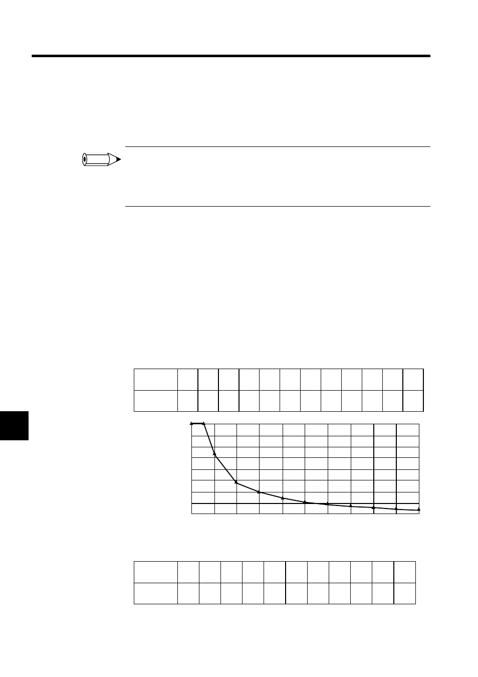
• For thick cables
• For thin cables
INFO
Distance
(m)
0
25
50
100
150
200
250
300
350
400
450
500
Max.
current (A)
8.00 8.00 5.42 2.93 2.01 1.53 1.23 1.03 0.89 0.78 0.69 0.63
0
0
1
2
3
4
5
6
7
8
50
100
150
200
250
300
350
400
450
500
Max. current (A)
Distance (m)
Distance
(m)
0
10
20
30
40
50
60
70
80
90
100
Max.
current (A)
3.00
3.00
3.00
2.06
1.57
1.26
1.06
0.91
0.80
0.71
0.64