Leds for status display – SMA SB 700U User Manual
Page 28
4-4
SMA America
SB700U-11:SE3207
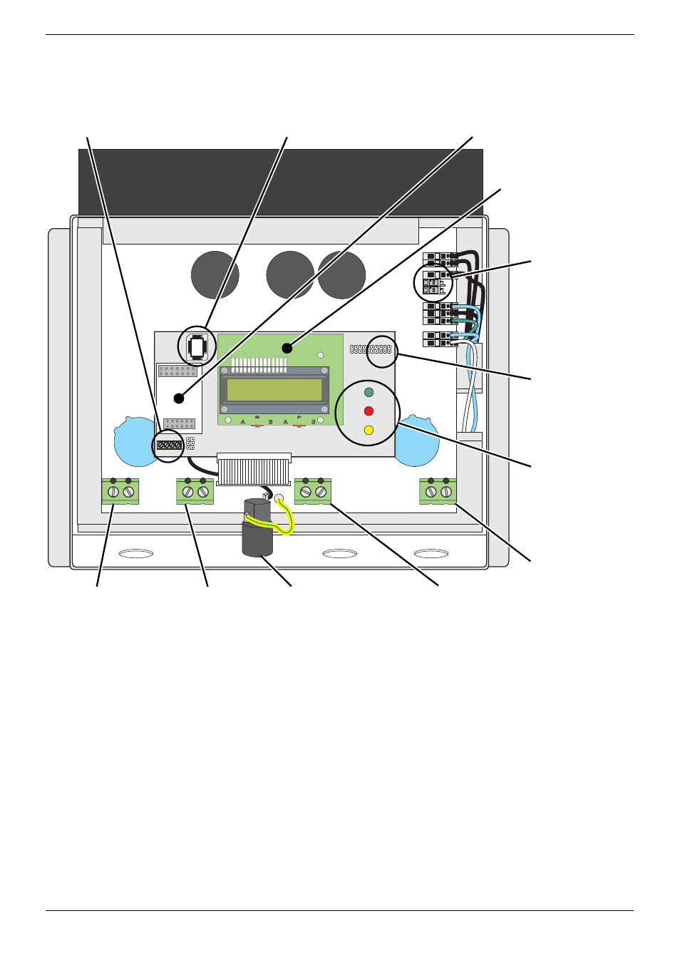
Figure 4-1 Sunny Boy 700U Internal Component Locator
The DC input from the PV array (via the DC disconnect enclosure) and the output to
the AC utility grid connect to the inverter inside the Sunny Boy’s case. These internal
AC and DC wiring terminals (see Figure 4-1) accept a maximum wire size of #6
AWG. Knockouts are provided on the bottom of the Sunny Boy near each of the
terminals for the wires to enter the case (Figure 4-2).
DC+
PE PE
L
N
ENS1
ENS2
S15
S1
3
S11
S
9
S7
S5
200V
150
V
2 3 5 7
DC
–
A
S2
A
B
B
S1
ı ˇ
ˇ
A
S2
A
B
B
S1
LEDs for
status display
Display
Terminal for optional
communication
(RS-485)
GFDI
Fuse Holder
AC Line
Terminals
(L and N)
Socket for optional
communication Piggy-Back
(RS-485 or wireless)
DC-Range
Configuration
Plug
DC-Range
Configuration
Jumper
Ground
Terminal
(PE)
Firmware EPROM
DC–
Terminal
(input from
PV array)
DC+
Terminal
(input from
PV array)
- SUNNY PORTAL (75 pages)
- SB 2.5-1VL-40 (60 pages)
- SB 2.5-1VL-40 Service Manual (36 pages)
- SB 240 (78 pages)
- FLX Pro 17 (12 pages)
- FLX Series GSM Option Kit (48 pages)
- FLX Series Sensor Interface Option (51 pages)
- FLX Series PLA Option (62 pages)
- FLX Series (248 pages)
- 25000TL (52 pages)
- 25000TL Installation (40 pages)
- 25000TL Service Manual (46 pages)
- CBL-DC-CMB8-10 (24 pages)
- 25000TL Quick Installation Guide (36 pages)
- STP 60-10 Replacing a Defective Fan (12 pages)
- STP 60-10 Replacing Defective Surge Arresters (12 pages)
- Webconnect Systems in SUNNY PORTAL (69 pages)
- STP 12000TL (68 pages)
- STP 60-US-10 Installation (232 pages)
- 485 Data Module Type B (24 pages)
- STP 12000TL Quick Installation Guide (28 pages)
- 1000-US (52 pages)
- STP 24000TL-US (78 pages)
- STP 17000TL (60 pages)
- STP 20000TL (2 pages)
- SB 6000TL Service Manual (46 pages)
- MULTIFUNCTION RELAY (32 pages)
- SB 5000TL (60 pages)
- SB 5000TL Quick Installation Guide (32 pages)
- FANKIT01-10 (24 pages)
- SB 7700TL-US (28 pages)
- FANKIT02-10 (24 pages)
- SB 7700TL-US Installation (96 pages)
- SUNNY MINI CENTRAL (48 pages)
- DC Disconnect Switch For SB 3800-U (32 pages)
- SB 4000-US (100 pages)
- DB-DC-DISCON (4 pages)
- SB 3800-U (86 pages)
- POWER BALANCER (28 pages)
- SB 8000-US (104 pages)
- SB 11000TL‑US (40 pages)
- SMC 11000TL (24 pages)
- SBCBTL6 (36 pages)
- SB 11000TL‑US Installation (92 pages)
- SMC 11000TL Installation (96 pages)