Incremental signals « ttl – HEIDENHAIN Length Gauges User Manual
Page 44
44
Incremental signals « TTL
HEIDENHAIN encoders with « TTL
interface incorporate electronics that
digitize sinusoidal scanning signals with
or without interpolation.
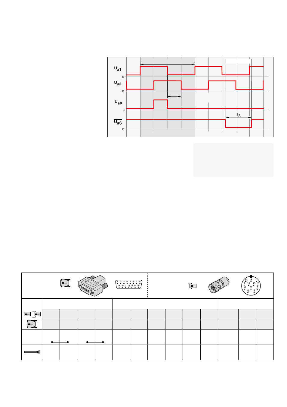
The incremental signals are transmitted
as the square-wave pulse trains U
a1
and
U
a2
, phase-shifted by 90° elec. The
reference mark signal
consists of one or
more reference pulses U
a0
, which are
gated with the incremental signals. In
addition, the integrated electronics produce
their inverted signals ¢, £ and ¤ for
noise-proof transmission. The illustrated
sequence of output signals—with U
a2
lagging U
a1
—applies to the direction of
motion shown in the dimension drawing.
The fault detection signal ¥ indicates
fault conditions such as an interruption in
the supply lines, failure of the light source,
etc.
The Interfaces of HEIDENHAIN
Encoders brochure, ID 1078628-xx,
provides comprehensive descriptions of
all available interfaces as well as general
electrical information.
The distance between two successive
edges of the incremental signals U
a1
and
U
a2
through 1-fold, 2-fold or 4-fold
evaluation is one measuring step.
Pin layout
15-pin
D-sub
connector
12-pin
HEIDENHAIN
connector
Voltage supply
Incremental signals
Other signals
12
2
10
11
5
6
8
1
3
4
7
/
9
4
12
2
10
1
9
3
11
14
7
13
5/6/8
15
U
P
Sensor
U
P
0 V
Sensor
0 V
U
a1
¢
U
a2
£
U
a0
¤
¥
1)
Vacant Vacant
2)
Brown/
Green
Blue
White/
Green
White
Brown
Green
Gray
Pink
Red
Black
Violet
–
Yellow
Shield
on housing; U
P
= Power supply
Sensor:
The sensor line is connected in the encoder with the corresponding power line.
1)
ERO 14xx: Vacant
2)
Exposed linear encoders: Switchover TTL/11 µA
PP
for PWT
Vacant pins or wires must not be used!
Color assignment applies only to extension cable.
Signal period 360° elec.
Fault
Measuring step after
4-fold evaluation
The inverse signals ¢, £, ¤ are not shown.