Interfaces incremental signals » 1 v – HEIDENHAIN Length Gauges User Manual
Page 43
43
Interfaces
Incremental signals » 1 V
PP
Pin layout
12-pin coupling,
M23
12-pin connector,
M23
15-pin D-sub connector
For ND 28x/PWM 20 or on encoder
Voltage supply
Incremental signals
Other signals
12
2
10
11
5
6
8
1
3
4
9
7
/
4
12
2
10
1
9
3
11
14
7
5/6/8/15
13
/
U
P
Sensor
U
P
0 V
Sensor
0 V
A+
A–
B+
B–
R+
R–
Vacant
Vacant Vacant
Brown/
Green
Blue
White/
Green
White
Brown
Green
Gray
Pink
Red
Black
/
Violet
Yellow
Shield
on housing; U
P
= Power supply
Sensor:
The sensor line is connected in the encoder with the corresponding power line.
Vacant pins or wires must not be used!
Color assignment applies only to extension cable.
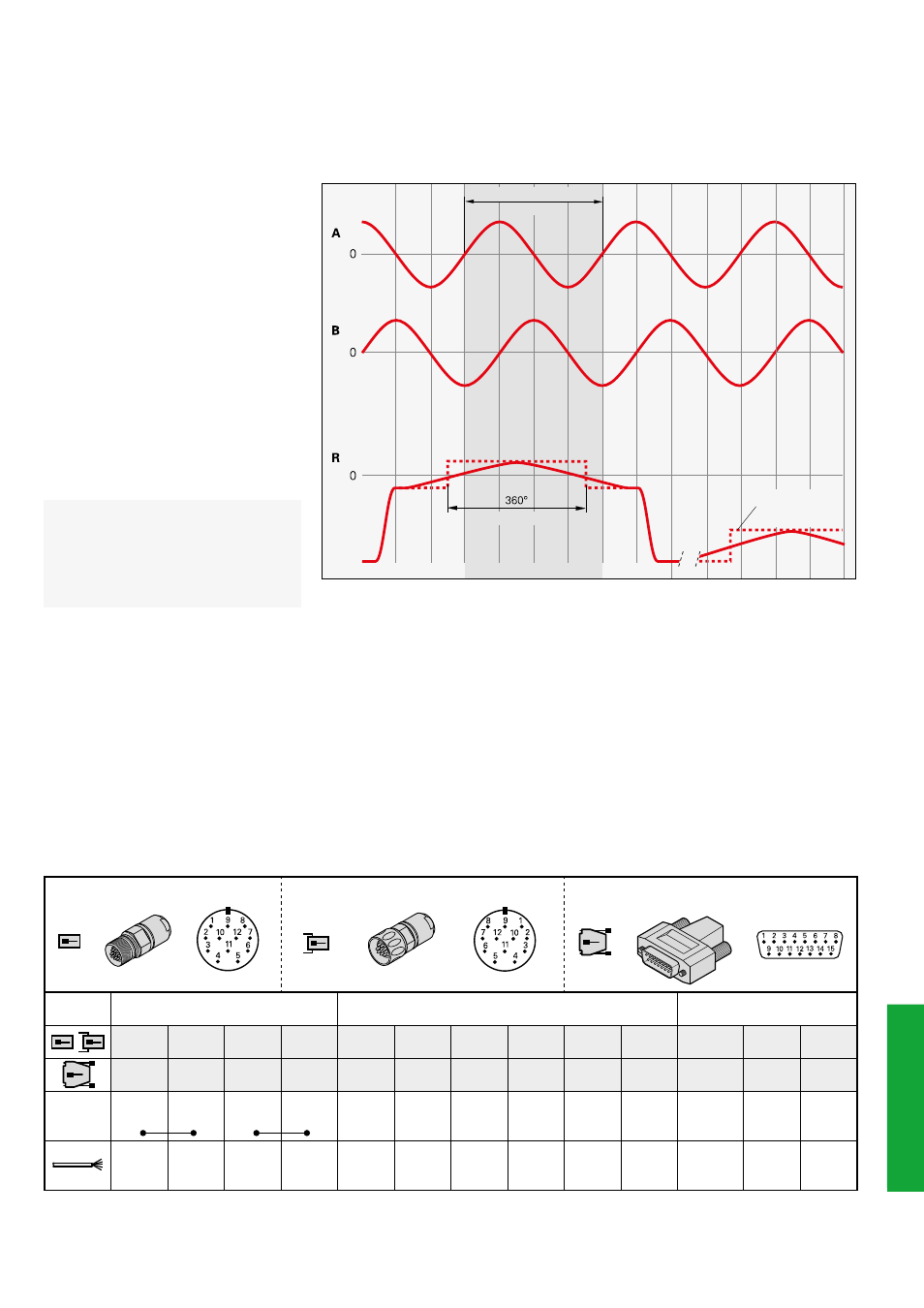
Signal period
360° elec.
(rated value)
A, B, R measured with oscilloscope in differential mode
HEIDENHAIN encoders with » 1 V
PP
interface provide voltage signals that can
be highly interpolated.
The sinusoidal incremental signals A and
B are phase-shifted by 90° elec. and have
amplitudes of typically 1 V
PP.
The illustrated
sequence of output signals—with B
lagging A—applies for the direction of
motion shown in the dimension drawing.
The reference mark signal R has an un-
ambiguous assignment to the incremental
signals. The output signal might be some-
what lower next to the reference mark.
Alternative signal
shape
The Interfaces of HEIDENHAIN
Encoders brochure, ID 1078628-xx,
includes comprehensive descriptions of
all available interfaces as well as general
electrical information.