HEIDENHAIN Length Gauges User Manual
Page 11
11
Imaging principle
To put it simply, the imaging scanning prin-
ciple functions by means of projected-light
signal generation: two scale gratings with
equal or similar grating periods are moved
relative to each other—the scale and the
scanning reticle. The carrier material of the
scanning reticle is transparent, whereas
the graduation on the measuring standard
may be applied to a transparent or reflec-
tive surface.
When parallel light passes through a
grating, light and dark surfaces are
projected at a certain distance. An index
grating is located here. When the two
gratings move relative to each other, the
incident light is modulated. If the gaps in
the gratings are aligned, light passes
through. If the lines of one grating coincide
with the gaps of the other, no light passes
through. An array of photovoltaic cells
converts these variations in light intensity
into electrical signals. The specially
structured grating of the scanning reticle
filters the light to generate nearly
sinusoidal output signals.
The smaller the period of the grating
structure is, the closer and more tightly
toleranced the gap must be between the
scanning reticle and scale.
The HEIDENHAIN-ACANTO, HEIDENHAIN-
SPECTO and the HEIDENHAIN-METRO
length gauges of the MT 60 and MT 100
series operating according to the imaging
principle.
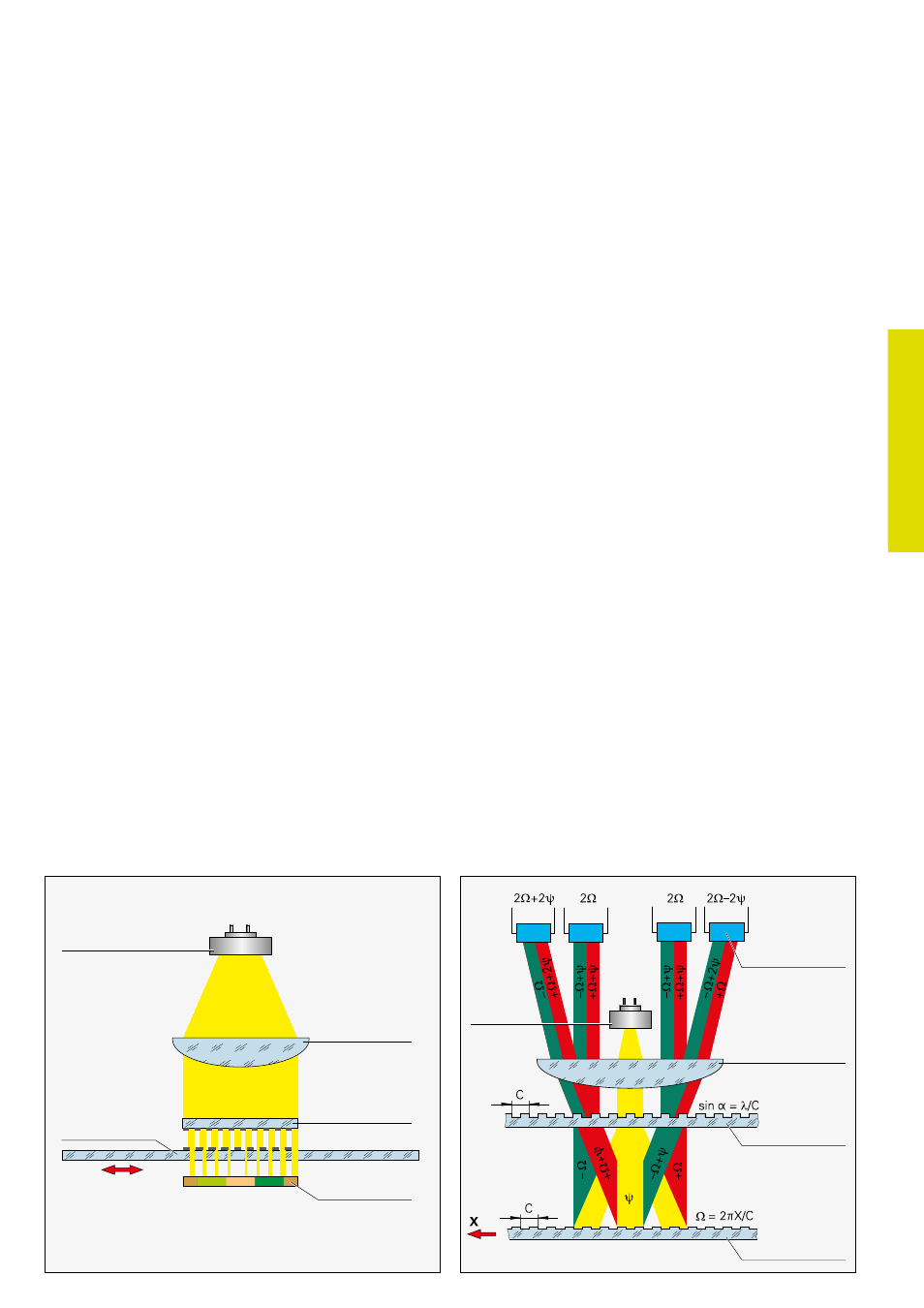
Imaging principle
LED light source
Measuring standard
Condenser lens
Scanning reticle
Photovoltaic
cell array
Interferential scanning principle
The interferential scanning principle
exploits the diffraction and interference of
light on a fine graduation to produce
signals used to measure displacement.
A step grating is used as the measuring
standard: reflective lines 0.2 µm high are
applied to a flat, reflective surface. In front
of that is the scanning reticle—a transpar-
ent phase grating with the same grating
period as the scale.
When a light wave passes through the
scanning reticle, it is diffracted into three
partial waves of the orders –1, 0, and +1,
with approximately equal luminous
intensity. The waves are diffracted by the
scale such that most of the luminous
intensity is found in the reflected diffraction
orders +1 and –1. These partial waves meet
again at the phase grating of the scanning
reticle where they are diffracted again and
interfere. This produces essentially three
waves that leave the scanning reticle at
different angles. Photovoltaic cells convert
this alternating light intensity into electrical
signals.
A relative motion of the scanning reticle to
the scale causes the diffracted wave fronts
to undergo a phase shift: when the grating
moves by one period, the wave front of the
first order is displaced by one wavelength
in the positive direction, and the wave-
length of diffraction order –1 is displaced by
one wavelength in the negative direction.
Since the two waves interfere with each
other when exiting the grating, the waves
are shifted relative to each other by two
wavelengths. This results in two signal peri-
ods from the relative motion of just one
grating period.
Interferential encoders function with
grating periods of, for example, 8 µm, 4 µm
and finer. Their scanning signals are largely
free of harmonics and can be highly
interpolated. These encoders are therefore
especially suited for high resolution and
high accuracy.
The HEIDENHAIN-CERTO and the
HEIDENHAIN-METRO length gauges
of the MT 1200 and MT 2500 series
operating according to the interferential
principle.
LED light
source
Measuring standard
Condenser lens
Scanning reticle
Photocells
Interferential scanning principle (optics schematics)
C Grating period
y Phase shift of the light wave when passing through the scanning reticle
Phase shift of the light wave due to motion X of the scale