Define a workpiece blank, 3 pr ogr amming the first p a rt – HEIDENHAIN TNC 620 (340 56x-02) User Manual
Page 40
40
First Steps with the TNC 620
1
.3 Pr
ogr
amming the First P
a
rt
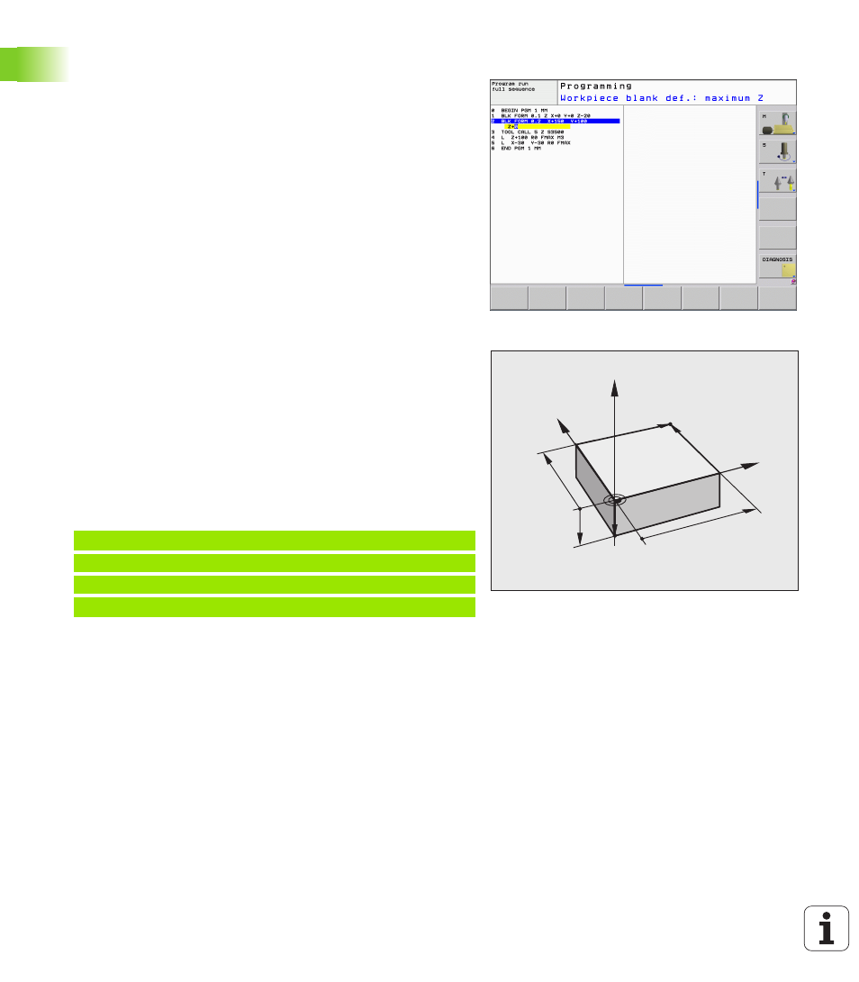
Define a workpiece blank
Immediately after you have created a new program, the TNC starts the
dialog for entering the workpiece blank definition. Always define the
workpiece blank as a cuboid by entering the MIN and MAX points,
each with reference to the selected reference point.
After you have created a new program, the TNC automatically initiates
the workpiece blank definition and asks for the required data:
U
Working plane in graphic: XY?
: Enter the active spindle axis. Z is
saved as default setting. Accept with the ENT key
U
Workpiece blank def.: Minimum X
: Smallest X coordinate of the
workpiece blank with respect to the reference point, e.g. 0. Confirm
with the ENT key.
U
Workpiece blank def.: Minimum Y
: Smallest Y coordinate of the
workpiece blank with respect to the reference point, e.g. 0. Confirm
with the ENT key.
U
Workpiece blank def.: Minimum Z
: Smallest Z coordinate of the
workpiece blank with respect to the reference point, e.g. -40.
Confirm with the ENT key.
U
Workpiece blank def.: Maximum X
: Largest X coordinate of the
workpiece blank with respect to the reference point, e.g. 100.
Confirm with the ENT key.
U
Workpiece blank def.: Maximum Y
: Largest Y coordinate of the
workpiece blank with respect to the reference point, e.g. 100.
Confirm with the ENT key.
U
Workpiece blank def.: Maximum Z
: Largest Z coordinate of the
workpiece blank with respect to the reference point, e.g. 0. Confirm
with the ENT key. The TNC concludes the dialog.
Example NC blocks
Further information on this topic
Defining the workpiece blank: (see page 82)
Y
X
Z
MAX
MIN
-40
100
100
0
0
0 BEGIN PGM NEW MM
1 BLK FORM 0.1 Z X+0 Y+0 Z-40
2 BLK FORM 0.2 X+100 Y+100 Z+0
3 END PGM NEW MM