HEIDENHAIN TNC 620 (340 56x-02) User Manual
Page 343
HEIDENHAIN TNC 620
343
1
1
.2 The PLANE F
unction: Tilting the W
o
rk
ing Plane (Sof
tw
ar
e Option 1)
U
Dist. tool tip – center of rot.
(incremental): The TNC tilts the
tool (or table) relative to the tool tip. The DISTANCE parameter shifts
the center of rotation of the positioning movement relative to the
current position of the tool tip.
U
Feed rate? F=
: Contour speed at which the tool should be
positioned
Positioning the rotary axes in a separate block
Proceed as follows if you want to position the rotary axes in a separate
positioning block (option STAY selected):
U
Select any PLANE function, and define automatic positioning with the
STAY
option. During program execution the TNC calculates the
position values of the rotary axes present on the machine, and
stores them in the system parameters Q120 (A axis), Q121 (B axis)
and Q122 (C axis)
U
Define the positioning block with the angular values calculated by
the TNC
NC example blocks: Position a machine with a rotary table C and a
tilting table A to a space angle of B+45°.
1
1
1
1
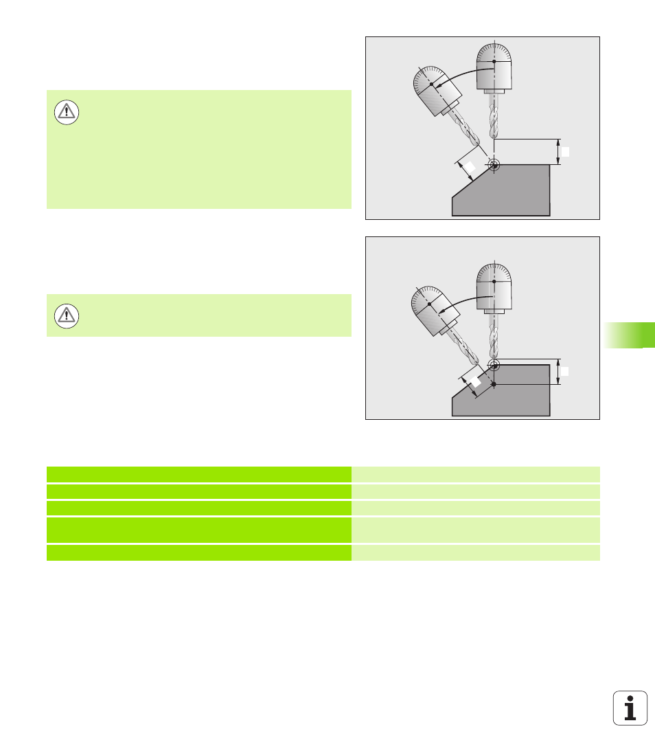
Note:
If the tool is already at the given distance to the
workpiece before positioning, then relatively speaking
the tool is at the same position after positioning (see
figure at center right,
1
= SET UP)
If the tool is not at the given distance to the workpiece
before positioning, then relatively speaking the tool is
offset from the original position after positioning (see
figure at bottom right,
1
= SET UP)
Pre-position the tool to a position where there is no danger
of collision with the workpiece (clamping devices) during
positioning.
...
12 L Z+250 R0 FMAX
Position at clearance height.
13 PLANE SPATIAL SPA+0 SPB+45 SPC+0 STAY
Define and activate the PLANE function
14 L A+Q120 C+Q122 F2000
Position the rotary axis with the values calculated by
the TNC
...
Define machining in the tilted working plane