Grass Valley RSE1 User Manual
Page 27
Stand-Alone Controller
RSE 1
22
Rev. 1 / 02.2002
5.1.3
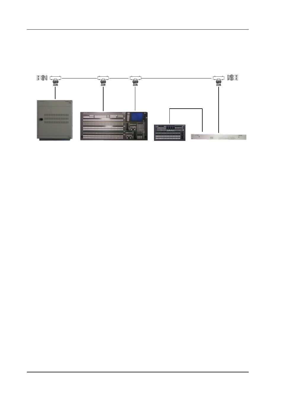
DD35 / SERAPH HD WITH RSAT2 AND RSE 1
5.1.3.1
Schematic
50
W
Terminator
BNC T-type
50
W
Terminator
BNC T-type
BNC T-type
BNC T-type
DD35 mainframe SD
RPS35-2S control panel
RSAT2
RSE1
5.1.3.2
Connecting the RSE1 to the Network
The RSE must be connected with the delivered Micro transciever to the switcher’s
network.
1. Connect the delivered Micro Transciever AT-MX 10S to the AUI / J18 port.
2. Connect a BNC cable to the switchers network (see above) and to the Micro
Transciever of the RSE1.
5.1.3.3
IP Addresses
The factory setting for the IP address (192.168.0.78) should avoid any conflict.
Nevertheless it is recommended to proceed in the normal way.
1. Look up the IP addresses of all devices
2. Check for conflict (i.e. two identical IP addresses).
The factory default setting avoids conflict, but better check twice.
3. If there is a conflict, select a free IP address and change the rotary hex switches
of the RSE1 accordingly.
Example: IP 192.168.0.16 (rotary switch setting 0x10).
Reset (or power cycle) the RSE 1.
5.1.3.4
Setting Up the RSE 1
To set up the RSE1 the sidepanel of the existing control panel is used.
The RSE1 must temporarily attached to the sidepanel.
1. Select menu Startup.
2. Open the Panel selection box with the Panel softkey.
3. Select the entry with the IP address of the RSE 1.