Grass Valley RSE1 User Manual
Page 25
Stand-Alone Controller
RSE 1
20
Rev. 1 / 02.2002
5.1.2
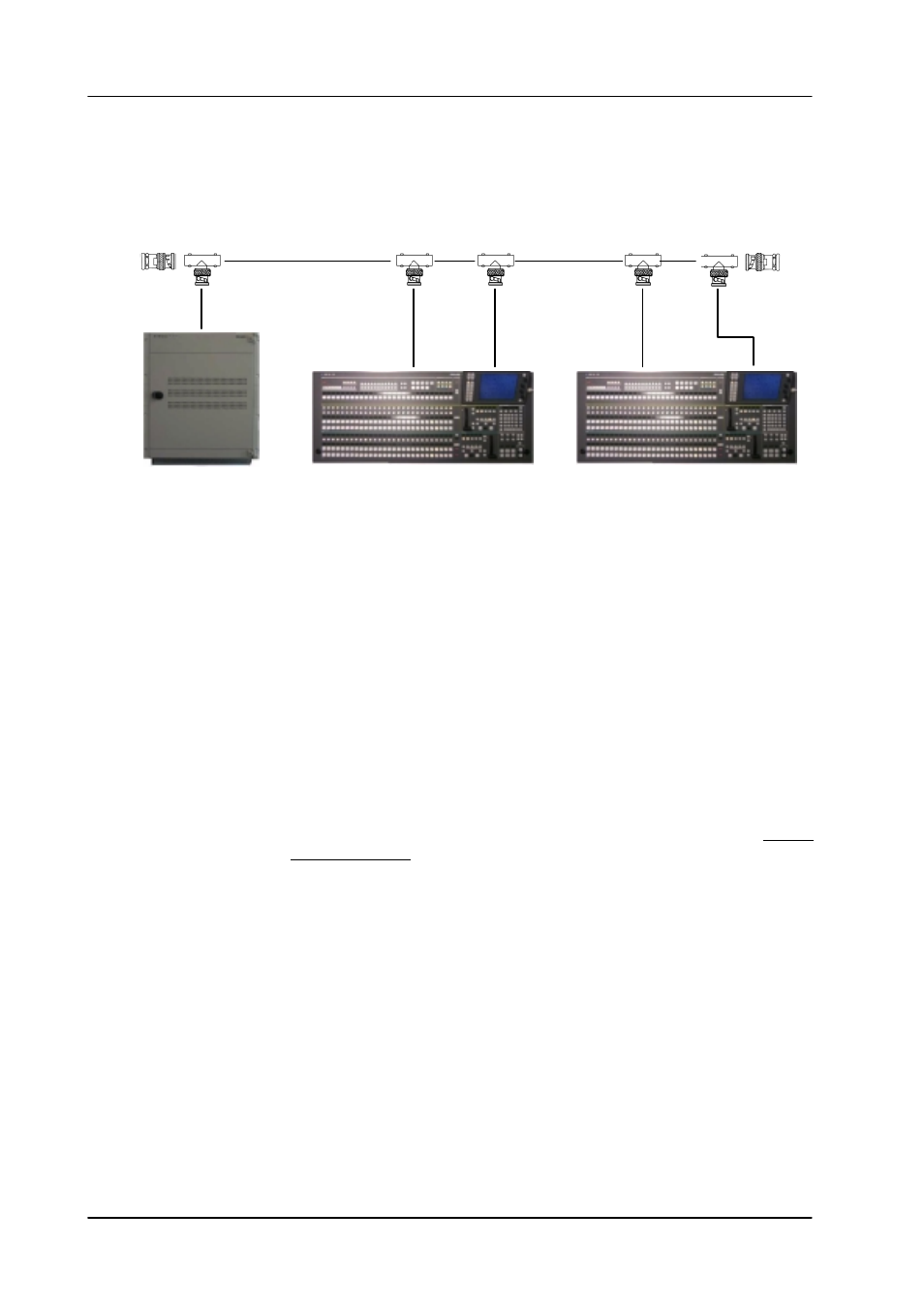
DD35 / SERAPH HD WITH TWO CONTROL PANELS
5.1.2.1
Schematic
50
W
Terminator
BNC T-type
50
W
Terminator
BNC T-type
BNC T-type
DD35 mainframe SD
RPS35-2S control panel
BNC T-type
BNC T-type
RPS35-2S control panel
The following assumes that the Control Panel (both LAN connectors) is connected
to the LAN.
5.1.2.2
IP addresses
As stated under ”Network Configuration” all devices on the LAN must have an uni-
que IP address.
To successfully integrate the second control panel (with its built-in sidepanel) in the
network take the steps as follows:
1. look up the IP addresses of all devices
2. check for conflict (i.e. two identical IP addresses).
If the second control panel has factory default setting then there is an address
conflict.
3. If there is a conflict, change the IP address of the second control panel and the
built-in sidepanel to free addresses.
The control panel address could be changed to 192.168.0.75 (rotary switch =
0x4B) and the sidepanel to 192.168.0.76. (by Windows
t
network settings).
In case the second control panel is ordered with initial order the factory sets up
those addresses.
4. Reboot the panel.
Both control panels operate fully in parallel.