Serial configuration port connection – Grass Valley 2000T3 User Manual
Page 34
34
Kameleon Frames Instruction Manual
Section 2 — Installation
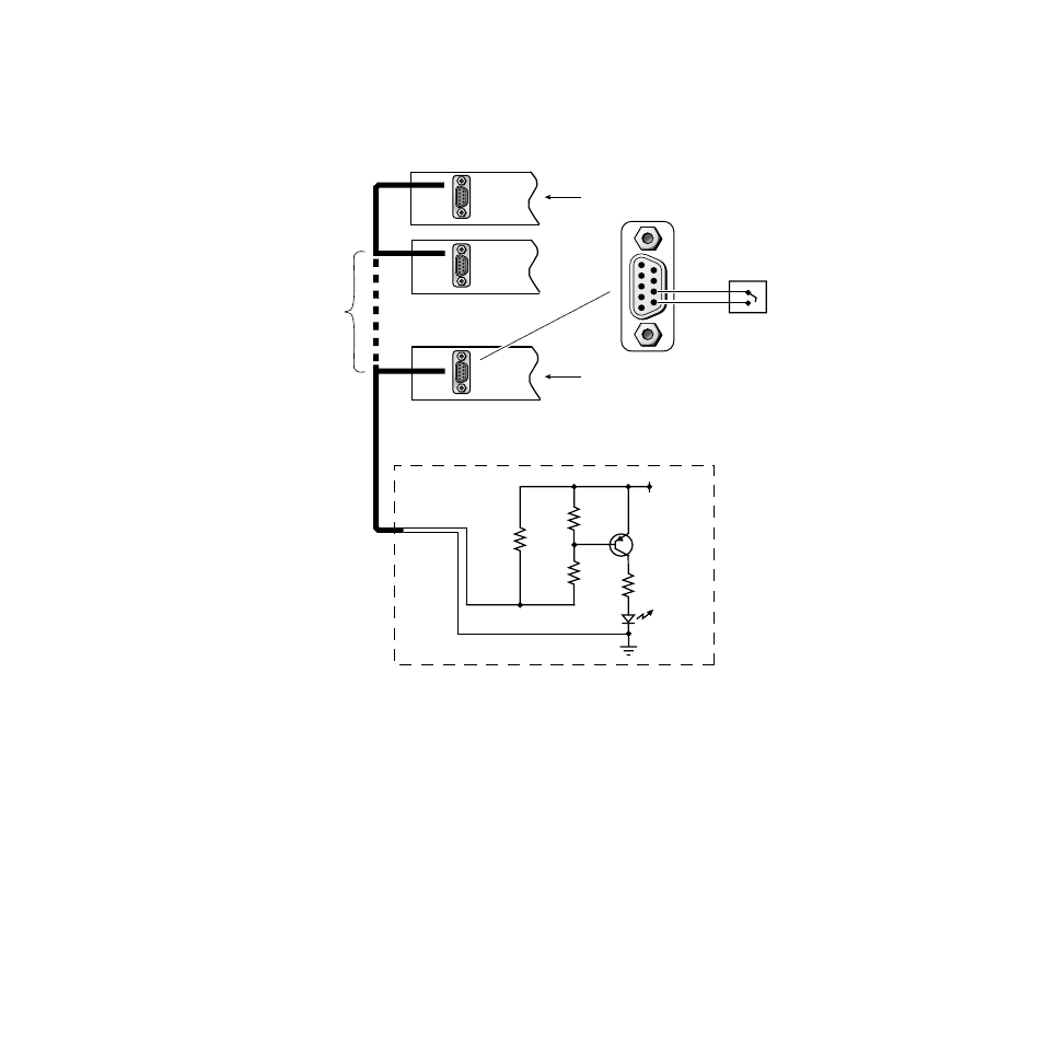
A number of frames can be coupled together as one alarm circuit. Refer to
for a typical alarm circuit interconnect diagram.
Figure 17. Frame Health Alarm Relay Connections
Serial Configuration Port Connection
On the 2000T3 frame, the female DB9 connector J101 is used to connect a
computer running terminal emulation to initially configure the frame for
networking. The 2000NET Network Interface Module is required to
support this connection. In the 2000T1 frame, the RJ-45 connector on the
front of the 2000NET is used for this function. Refer to the 2000NET
Network Interface Module Instruction Manual for details.
J103
Last Frame
First Frame
Health Alarm Circuit
Pin 8
Pin 9
Normally
open relay
+5V
4.7 kΩ
4.7 kΩ
330 Ω
470 Ω
To pin 8
To pin 9
Alarm
LED
2N4126
(or equivalent)
Up to 20 Frames
J103
J103
J103
8039-14