Frame health alarm connector (2000t3 only) – Grass Valley 2000T3 User Manual
Page 33
Kameleon Frames Instruction Manual
33
Module Installation
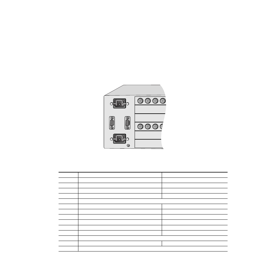
Frame Health Alarm Connector (2000T3 only)
The frame health alarm provides a relay closure that will act as an alarm
trigger for a user-supplied alarm circuit. The relay is accessed through con-
nector J103 SER3/GPI shown in
The frame health alarm responds to conditions enabled on the 2000NET
Network Interface module with DIP switches S1 and S2 as given in
.
This information from the module is also available over the network to an
SNMP monitoring system as described in detail in the 2000NET Instruction
Manual.
Figure 16. Frame Health Alarm Connector Location
Table 3. 2000NET Configuration DIP Switches, S1 and S2
S1 Segment
Left Position (open)
Right Position (closed)
1
PS1 fault reporting enabled
PS1 fault reporting disabled
2
PS2 fault reporting enabled
PS2 fault reporting disabled
3
PS3 fault reporting enabled
PS3 fault reporting disabled
4
PS4 fault reporting enabled
PS4 fault reporting disabled
5
(Currently not used)
6
Fan fault reporting enabled
Fan fault reporting disabled
7
Module fault reporting enabled
Module fault reporting disabled
8
Frame Bus fault reporting enabled
Frame Bus fault reporting disabled
S2 Segment
Left Position (open)
Right Position (closed)
1
Asynchronous Status Enabled (enabled alarms are reported over SNMP)
SNMP Reporting is disabled except for Over Temp alarm
2
Net module remote control enabled
Net module remote control disabled
3
(Currently not used)
4
Frame remote control enabled
Frame remote control disabled
5-8
(Currently not used)
Power,
Frame Configuration,
and Frame Health
Connectors
J 1 0 1
J 2
J 1
J 1 0 3
GND
SER 1
CONFIG
SER 3
GPI
8039-13