Cabling the intuition xg-e unit, Cabling the intuition xg-e unit -8 – Grass Valley Intuition XG Installation v.5.0 User Manual
Page 37
2-8
Intuition XG Installation & Quick Start Guide
Installation instructions for the Intuition XG-e
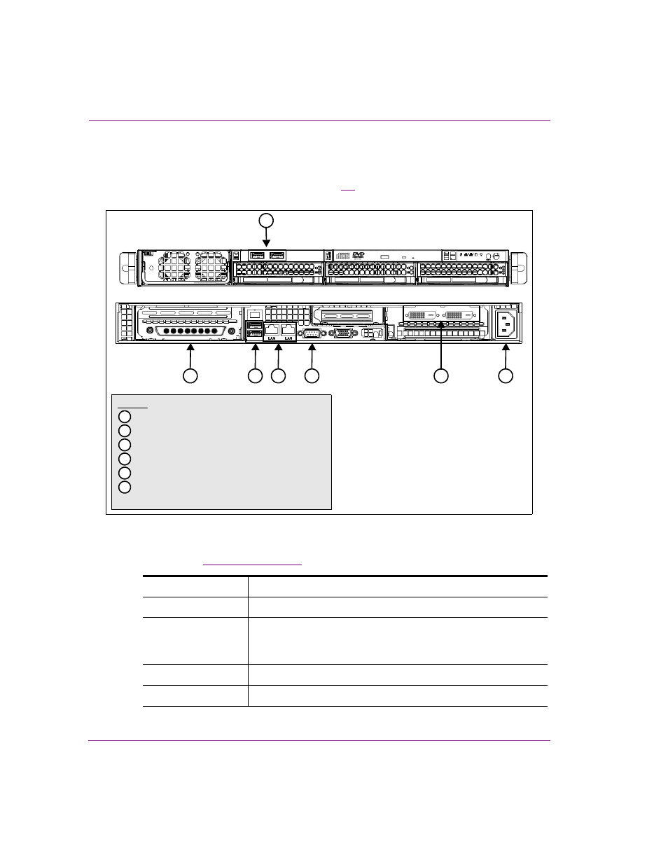
Cabling the Intuition XG-e unit
Once the Intuition XG-e chassis is securely mounted in an equipment rack, you can connect
the required cables to the rear connectors. Figure
and the cabling procedure provide step-
by-step instructions for properly cabling the Intuition XG-e unit.
Figure 2-1. Cabling the Intuition XG-e
To cable the Intuition XG-e:
1.
Connect the
to the Intuition XG’s SDI Video card I/O connector.
SDI IN A
Primary SDI program input connection for the Intuition XG-e unit.
SDI IN B
Not used on an Intuition XG-e unit.
SDI OUT A (F
ILL
1)
Primary output channel connection for the Intuition XG-e unit.
For the purposes of this setup procedure, connect this cable to a
broadcast monitor.
SDI OUT B
Not used on an Intuition XG-e unit.
SDI OUT C / K
EY
The matching key signal for SDI OUT A.
Legend
2
*
The numbers correspond to the steps in the cabling procedure
1
SDI Video I/O connector
2
Mouse & keyboard connectors
3
Ethernet Network connectors
4
Automation system connection (RS-232)
5
DVI Monitor connectors
6
Power supply
2
1
3
4
5
6