Local onboard module configuration, Local onboard module configuration on – Grass Valley 8960ENC v.8.1.0 User Manual
Page 22
22
8960ENC—Instruction Manual
Configuration
Local Onboard Module Configuration
The 8960ENC module can be configured locally using the rotary and toggle
switches shown in
. Two LEDs (CONF and 2nd) indicate status of
the configuration process. These four components perform the following:
•
Function (rotary) switch addresses a desired function for configuration
and provides two sets (banks) of 16 functions (0 through 9,
A through F), although not all positions are used.
•
2nd (second function) LED when on, indicates that the rotary switch is
addressing the second (Bank 2) of functions (see
)
that control the optional 8900FSS Frame Sync Submodule.
•
SW1 (paddle) switch actuates or selects the desired setting for the
selected function when the switch is held momentarily in either the up
or down position.
•
CONF (configuring) LED when on, indicates the module is initializing
or processing configuration information.
Note
Function switch position F (Recall) in Bank 1 can be used to return the
module configuration to the factory default.
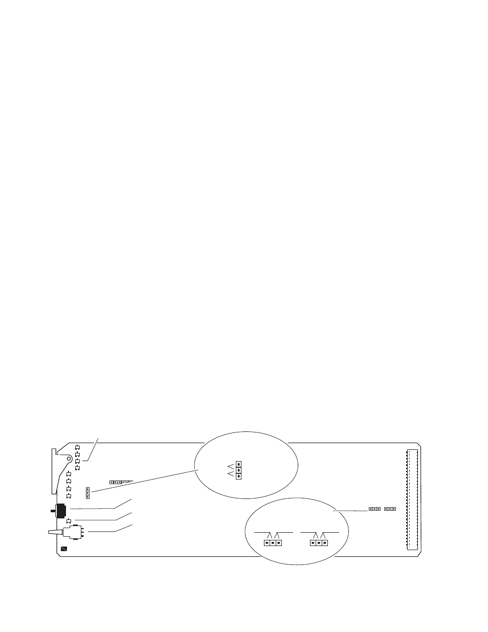
The following onboard jumpers are used to permit or lockout remote
control and set reference input impedance.
•
Remote Control Lockout – When a jumper is placed across pins 1 and 2
of jumper block JP1 (see
), module output mode settings are
adjustable from the Local on-board switches only. To have both Local
and Remote access, set the jumper across pins 2 and 3.
•
Reference Input Impedance – When a jumper is placed across pins 1
and 2 of jumper block JP10 (525 line reference) or JP11 (625 line refer-
ence), Reference Input is terminated into 75 Ω (see
). To have
high impedance termination, set the jumper across pins 2 and 3 of the
appropriate jumper block.
Figure 8. Module Configuration Switches, LEDs, and Jumpers
GRASS VALLEY GROUP 8 9 6 0 E N C C O M P O S I T E E N C O D E R 6 7 1 - 4 6 9 8 -
GND
FUNCTION – rotary switch
SW1 – actuator toggle switch
2nd – second function LED
CONF – configuration LED
JP1 Place jumper in
Local position to
lock out remote
access.
Local
Local &
Remote
JP1
JP10
JP11
Remote Lockout
Reference Input
Impedance
75 Hi
Z
JP11 (625)
75 Hi
Z
0642_07r1