Power up, Operation indicator leds – Grass Valley 8960ENC v.8.1.0 User Manual
Page 16
16
8960ENC—Instruction Manual
Power Up
Power Up
The front LED indicators and configuration switches are illustrated in
. Upon power-up, the green PWR LED should light and the yellow
CONF LED should illuminate for the duration of module initialization.
Note
When a media module is first plugged into a Gecko or GeckoFlex frame, the
8900NET module (if present) may report a momentary fault. This will clear
once the media module has booted up.
Operation Indicator LEDs
With factory default configuration and a valid input signal connected, the
green PWR LED, the yellow AUTO, and one of the green signal standard
LEDs (525 or 625) should illuminate (refer to
to see the
possible operating indicator combinations).
Video input presence is indicated by the 525 or 625 LED (indicating a
525-line or 625-line input signal has been detected). The AUTO LED indi-
cates that automatic standard selection is enabled.
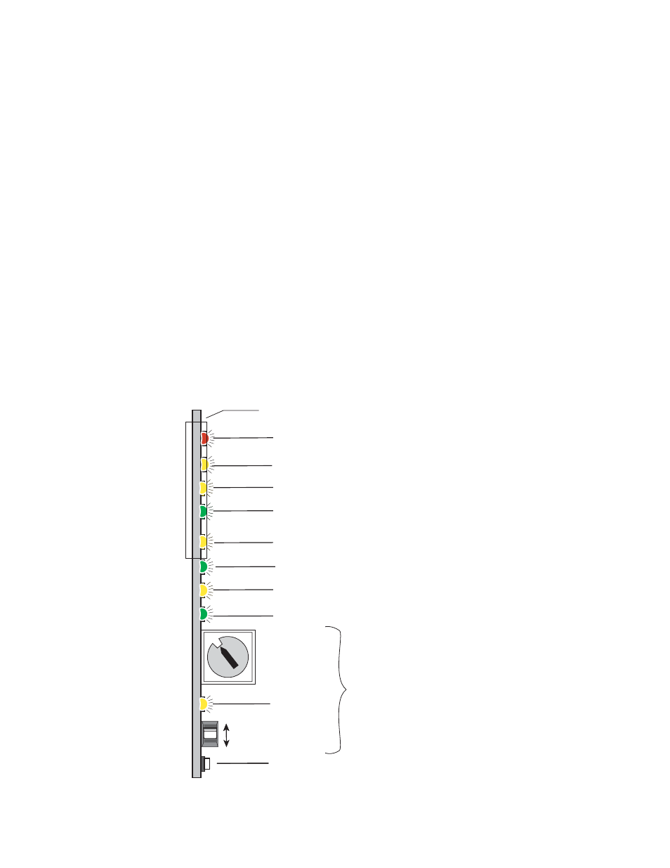
Figure 7. LEDs and Configuration Switches
0642_06r1
0
1
2
3
4 5 6
7
8
9
A
B
C
D
16-position
Rotary switch
Momentary toggle switch
525 – Green LED on indicates 525-line input is present
PWR – Green LED on indicates power OK
FAULT – Red LED is off during normal operation
Ejector Tab
COMM – Yellow LED indicates communication activity
CONF – Yellow LED indicates configuration activity
Auto/Manual MODE – Yellow LED on indicates automatic input detection mode
625 – Green LED on indicates 625-line input is present
Filter – Yellow LED on indicates signal is being cross-color filtered
Module Configuration Switches and LED
GND
2nd Function
(yellow)