H3C Technologies H3C S3600V2 Series Switches User Manual
Page 56
50
Status
LED
System status
LED (SYS)
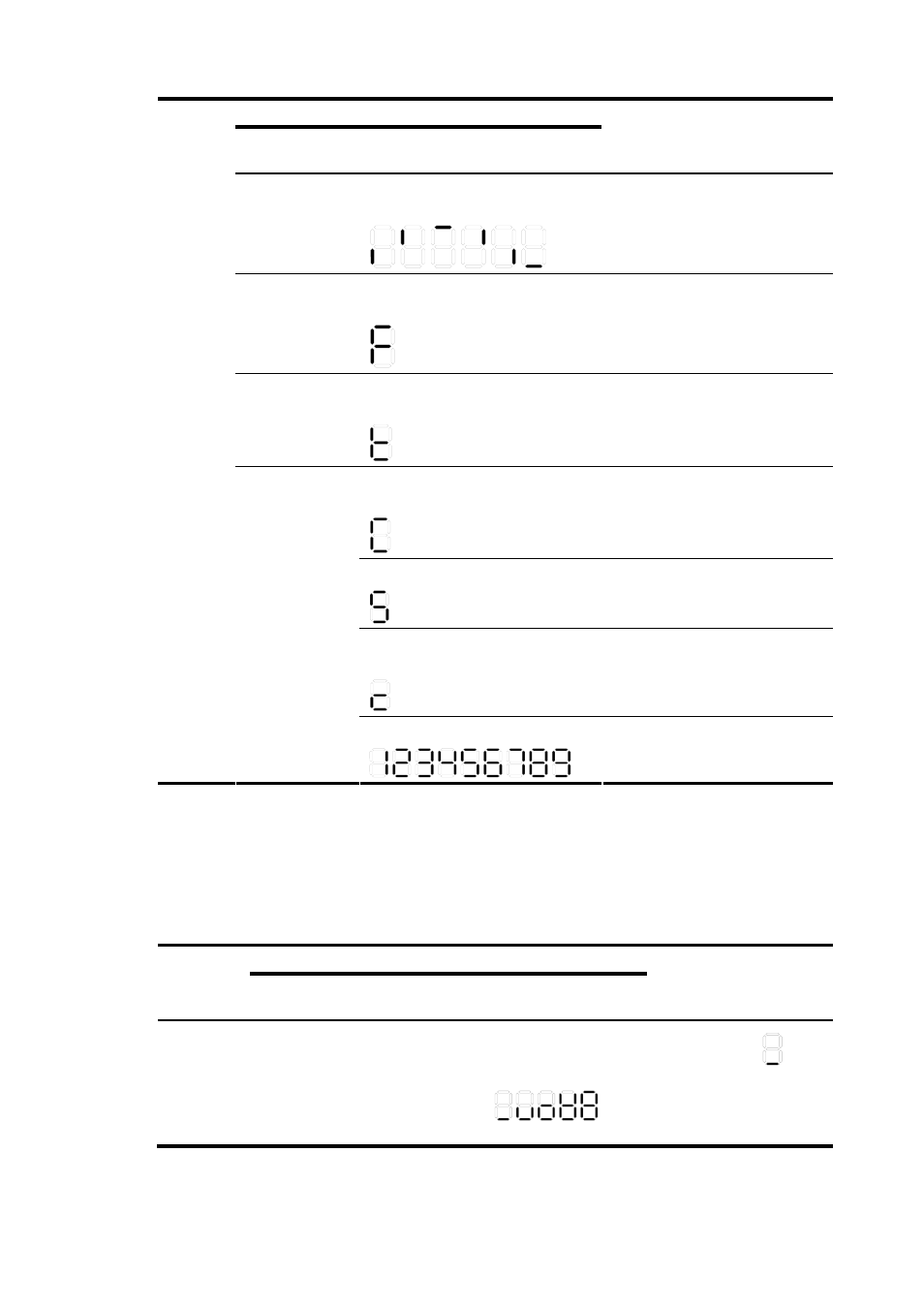
Seven-segment (Unit) LED
Description
Flashing green
A bar rotates clockwise around the
LED.
Software is loading.
Steady red
The LED displays a flashing F
character.
The switch is experiencing a fan
failure.
Steady red
The LED displays a flashing t
character.
The switch is in an over-temperature
condition.
The LED displays a capital C
character.
The switch is the command switch in
a cluster.
The LED displays an S character.
The switch is a member switch in a
cluster.
The LED displays a lowercase c
character.
The switch is a candidate switch for
a cluster.
Steady green
The LED displays a number.
The member ID of the switch.
On the S3600V2-28TP-PWR-EI, S3600V2-28TP-PWR-SI, S3600V2-52TP-PWR-EI or
S3600V2-52TP-PWR-SI switch, the seven-segment LED can also show the total PoE output power as a
percentage of the maximum PoE output power that the switch can supply (see
Table 20 Seven-segment LED description (II)
Status
LED
Port mode LED System status
LED
Seven-segment (Unit)
LED
Description
Unit
Flashing green
(1 Hz) (PoE
mode)
Steady green
The LED displays
different signs.
0 - 20%
21 - 40%
41 - 60%
61 - 80%
81 - 100%
For example, the
sign
indicates that the switch is
outputting 0 to 20% of the
maximum PoE output
power.