Grounding the switch, Grounding cable, Grounding the switch with a grounding strip – H3C Technologies H3C S3600V2 Series Switches User Manual
Page 20
14
Step3
Attach the rubber feet to the four round holes in the chassis bottom.
Step4
Place the switch with upside up on the workbench.
IMPORTANT:
•
Ensure good ventilation and 10 cm (3.9 in) of clearance around the chassis for heat dissipation.
•
Avoid placing heavy objects on the switch.
Grounding the switch
WARNING!
Correctly connecting the switch grounding cable is crucial to lightning protection and EMI protection.
NOTE:
The power and grounding terminals in this section are for illustration only.
The power input end of the switch has a noise filter, whose central ground is directly connected to the
chassis to form the chassis ground. You must securely connect this chassis ground to the earth so that the
faradism and leakage electricity can be safely released to the earth to minimize EMI susceptibility of the
switch.
You can ground the switch in one of the following ways, depending on the grounding conditions
available at the installation site:
•
Grounding the switch with a grounding strip
•
Grounding the switch with a grounding conductor buried in the earth ground
•
Grounding the switch with the PE wire of an AC power supply
Grounding cable
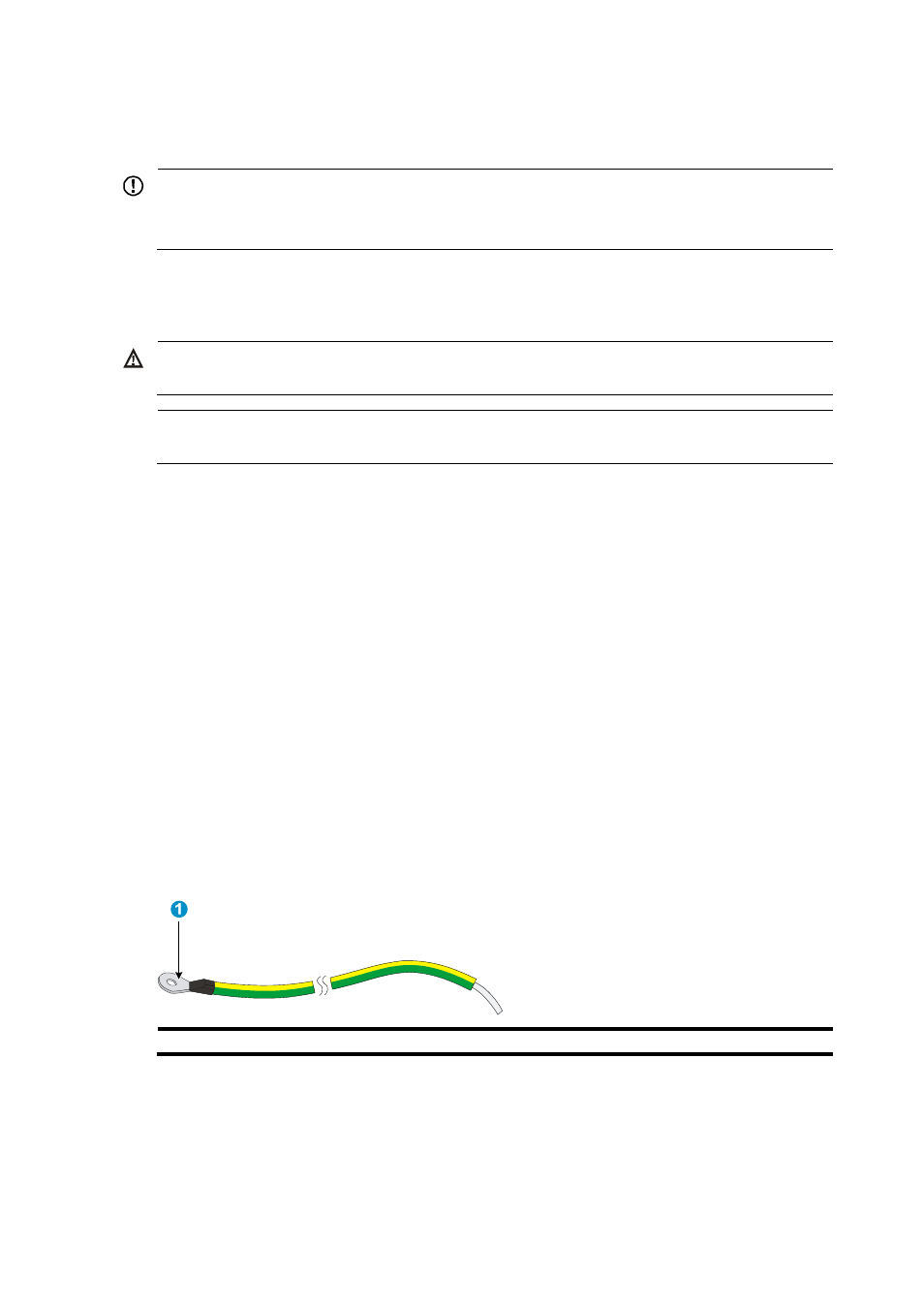
The S3600V2 Switch Series is provided with a yellow-green grounding cable. One end of the cable has
an OT terminal, and the other end is naked and soldered, as shown in
.
Figure 20 Grounding cable
(1) OT terminal of the grounding cable
Grounding the switch with a grounding strip
When a grounding strip is available at the installation site, connect the grounding cable to the
grounding strip.