Airaid 250-252 User Manual
Page 2
Airaid Filter Co. 2688 E Rose Garden Ln. Phoenix AZ 85050 (800) 498-6951
REV.05.20.14
P/N 790-551 Aerosol Spray
P/N 790-550 Squeeze Spray
Thank you for purchasing the Airaid Intake System. Contact Airaid @ (800) 498-6951 8:00 AM - 5:00 PM MST weekdays for questions
regarding fit or instructions that are not clear to you. Your Airaid Intake System was carefully inspected and packaged. Check that no parts are
missing, or were damaged during shipping. If any parts are missing, contact Airaid. The air filter element is protected from direct exposure to wa-
ter and debris; care should be taken not to drive through deep water. WATER INGESTION IS THE DRIVERS RESPONSIBILTY! The air filter is
reusable and should be cleaned periodically.
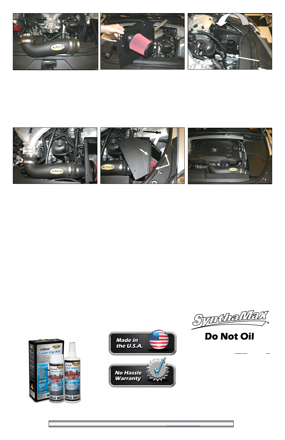
11. A) Install the Bracket (#25) on to the Rear Panel
(#4) as shown using one 1/4-20 Button Head Screw
(#15), 1/4” Flat Washer (#16), and 1/4” Serrated Nut
(#17).B) Complete the assembly by attaching the Airaid
Premium Filter (#1) to the Mass Air Flow Sensor.
12. A) Lower the Airaid Performance Air box assembly
into the engine cavity . Insert the Well Nut into the Fac-
tory core support grommet and rotate the assembly rear-
ward until the bracket rests on the shock tower and the
MAF panel’s lower tab hole is lined up with the Tapped
Chassis bolt hole. B) Secure the assembly by using the
1/4-20x 1/2 Bolt(#15). NOTE: If your vehicle did not
require cutting threads in step 5, and has a ground cable,
you will reuse the factory bolt. Remove the ground cable
bolt and slide the panel between the chassis and the
ground terminal. Re secure the entire assembly using the
factory supplied 6mm bolt.
13.A) Install the Airaid Intake Tube assembly onto the
Mass Air Flow Sensor first, and then onto the throttle
body. Adjust for fit, and tighten the hose clamps. B)
Replace the factory breather line on the valve cover with
the 26” Airaid Breather Hose(#11). Secure the breather
hose to the intake tube nipple using the black Speed
Clamp (#29)
14. A) Slide the Edge Clip Cable Ties (#30) about 6”
apart along the fender pinch weld and return the coolant
line to it’s original location. Secure the coolant line us-
ing the cable ties and trim off excess. B) Install the 8”
Weather Strip (#26) onto the curved edge of the top cov-
er (#6) and install the top cover onto the Airaid filter box
using the four 1/4-20 Black screws.(#21). C) Line up the
intake bracket with the fender bolt hole, and secure the
assembly using the factory bolt. Note: These steps must
be performed in order to avoid difficulty with bolt
hole alignment.
15. Reinstall the Factory engine and shock tower covers.
Reconnect the negative battery cable
.
Dou-
ble check your work!
Make sure there is no foreign material in the
intake path. Make sure all clamps, hoses, bolts,
and screws are tight. Double check the hood
clearance.
B
10. Install the Reducer Coupler (#8)onto the 90 deg.
Bend of the Airaid Intake Tube (#2) and place and the
Hump Hose on the opposite end as shown. Secure the
couplers to the Intake Tube using the two #64 clamps
(#22). Place the #48 clamp(#24) on the reducing coupler
and the remaining #52 clamp(#23) on the Hump Hose.
A
C
B
A
B
A
FILTER IDENTIFICATION
700-452 Airaid Oiled Media 701-452 Airaid SynthaMax Dry Media - Red
702-452 Airaid SynthaMax Dry Media - Blue 703-452 Airaid SynthaMax Dry Media - Blue
For your Oiled media filter
we suggest using the AIRAID
Filter Tune-Up Kit!
Synthamax Air Filters do not require oil.
Service air filter as needed by cleaning with
common non-petroleum all-purpose house-
hold cleaner and water. Simple Green®,
Formula 409® or equivalent works great.
Apply cleaner to outside of air filter and al-
low to soak. Then flush filter clean from the
inside out with a garden hose and repeat
steps if necessary. Do not apply high pres-
sure water or air to clean filter. Allow filter
to air dry and reinstall
.