Verilink HDM 2180 (880-503048-001) Product Manual User Manual
Page 18
HDM 2180 DS3 DSU Overview
1-8
Verilink HDM 2180 User Manual
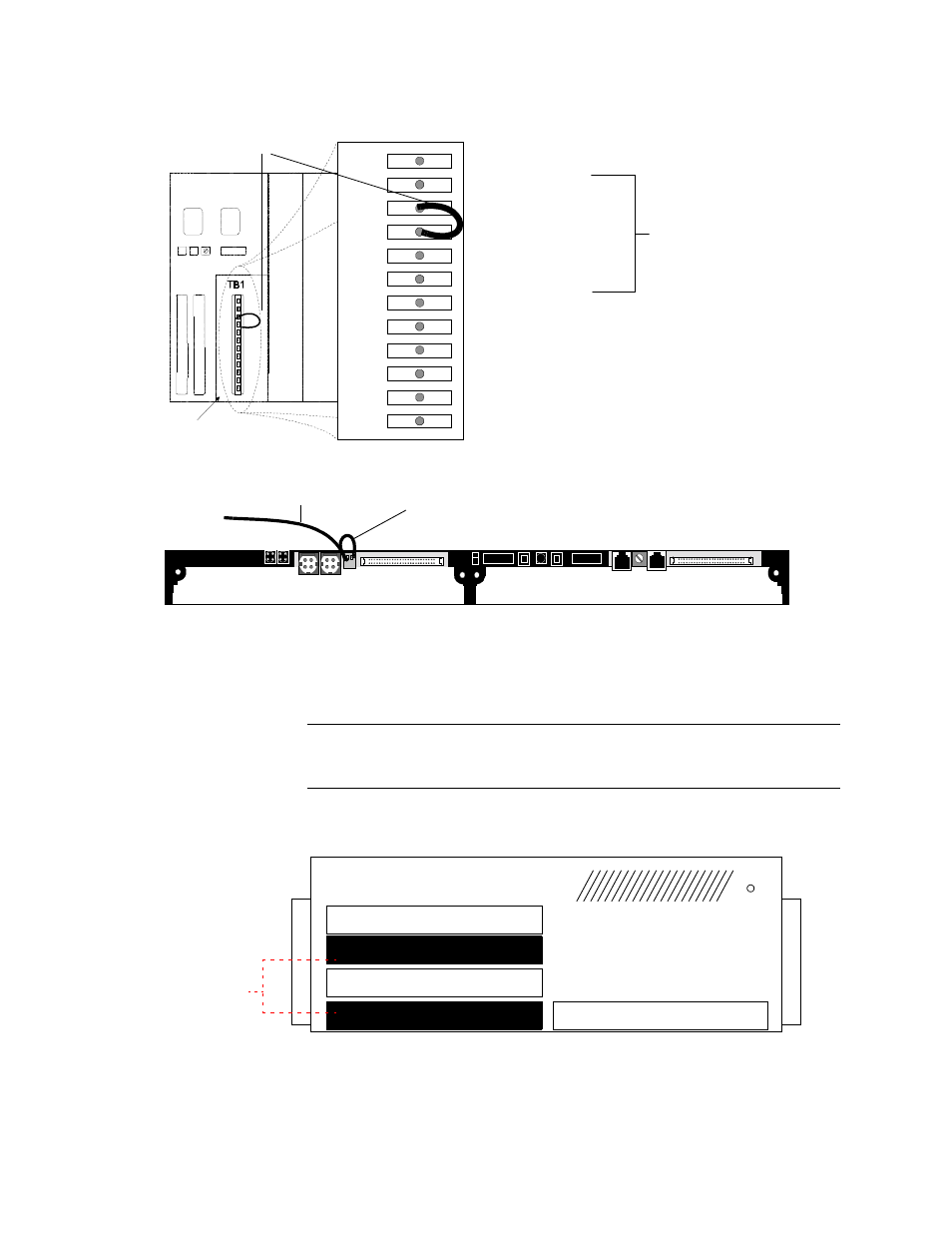
Figure 1-6 Terminal Block One on the MLS—Chassis Ground Connected to Signal Ground
Figure 1-7 Terminal Block One on a DLS (back view) Showing Ground Connection
The application card has the signal ground and chassis ground
terminals connected within the printed circuit board. This
additional connection has been made to prevent generation of
unwanted electromagnetic interference (EMI).
NOTE: When using the HDM modules in a Quint-line Shelf, be sure to
leave open slots between the modules to allow for proper air
circulation and heat dissipation (
).
Figure 1-8 HDM Usage in Quint-line Shelf
S i g n a l G r o u n d
R e m o v e c o v e r
fo r a c c e s s
1
2
3
4
5
6
7
8
9
1 0
11
1 2
1 2 R T N
C G N D
C G N D
G N D
G N D
G N D
4 8 R T N B
4 8 R T N A
4 8 B
4 8 B
4 8 A
4 8 A
4 8 V o l t R e tu rn B
4 8 V o l t R e tu rn A
4 8 V o l t B
4 8 V o l t B
4 8 V o l t A
4 8 V o l t A
1 2 V o l t R e tu rn
C h a s s is G ro u n d
C h a s s is G ro u n d
S i g n a l G r o u n d
S i g n a l G r o u n d
T i e S ig n a l a n d
C h a s s is G N D
to g e th e r fo r s i n g le
in s ta lla tio n s .
Jumper Wire
e
Ground Connection
To Ground
P 3
E x p a ns io n B u s
P 4
E x p a ns io n B u s
C A U T IO N
HDM placement in Quint-line Shelf—limit use to slots 1 and 3 or 2 and 4 ONLY. Be sure
to have open slots between the HDM modules for proper air circulation and heat dissipation.
Empty Slots
HDM 2180
NCM or other module
HDM 2180