3 general operation and conventions, Introduction, Dds csu/dsu front panel – Verilink FrameStart FSD (34-00291.F) Product Manual User Manual
Page 23: Chapter 3, general operation and, Conventions, Eneral, Peration, Onventions
G e n e r a l O p e r a t i o n a n d C o n v e n t i o n s
17
C
H A P T E R
3
C
HAPTER
3
G
ENERAL
O
PERATION
AND
C
ONVENTIONS
Introduction
This chapter describes the front panel buttons, LEDs, and conventions for the
LCD interface.
DDS CSU/DSU Front Panel
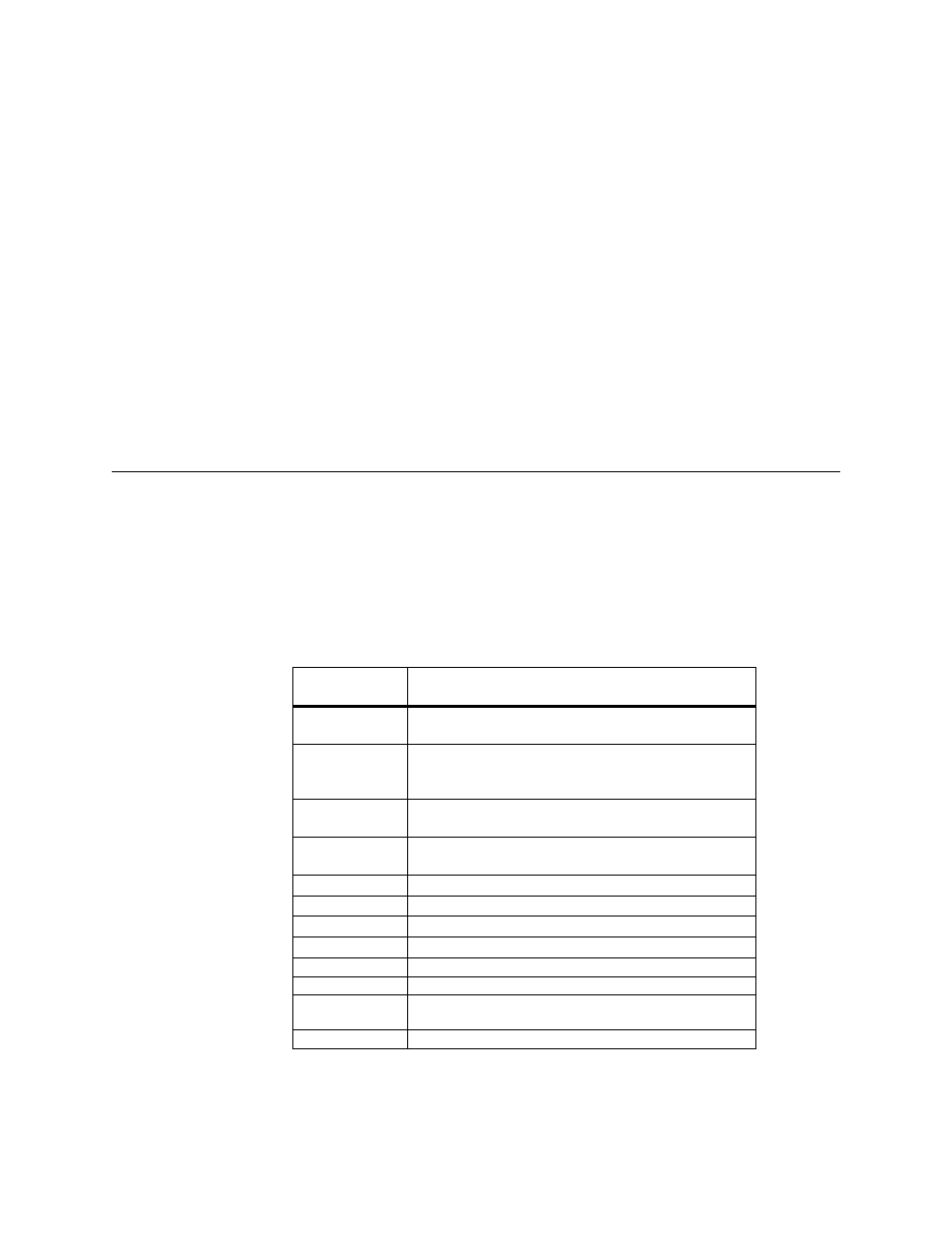
Table 3.1 references the front panel controls and indicators and provides a
brief description.
Table 3.1
Front Panel Controls and Indicators
Control or
Indicator
Function
liquid crystal
display
This 2-line, 16-character display provides access to unit
alarms, configuration, diagnostics, and utilities.
EXIT
The EXIT button allows exiting a menu option which then
places the unit in the next higher level in the menu hierarchy.
If in the main menu, pressing EXIT logs off the unit.
SCROLL
The SCROLL button allows reviewing the available options
or selections for a given level in the menu hierarchy.
SELECT
The SELECT button allows choosing the option or value for
a given field.
RTS (green)
This indicator is on when RTS is active.
DTR (green)
This indicator is on when DTR is active.
DCD (green)
This indicator is on when DCD is active.
TxD (green)
This indicator is on when the unit transmits data.
RxD (green)
This indicator is on when the unit receives data.
TEST (yellow)
This indicator is on when the unit is in a test mode.
ALARM (red)
This indicator turns on when the unit is in an active alarm
condition.
POWER (green)
This indicator turns on when power is applied to the unit.