Data connections, V.35 data port, Dds csu/dsu network port – Verilink FrameStart FSD (34-00291.F) Product Manual User Manual
Page 19: T1 csu/dsu and framestart fse network connection
I n s t a l l a t i o n
13
Data Connections
V.35 Data Port
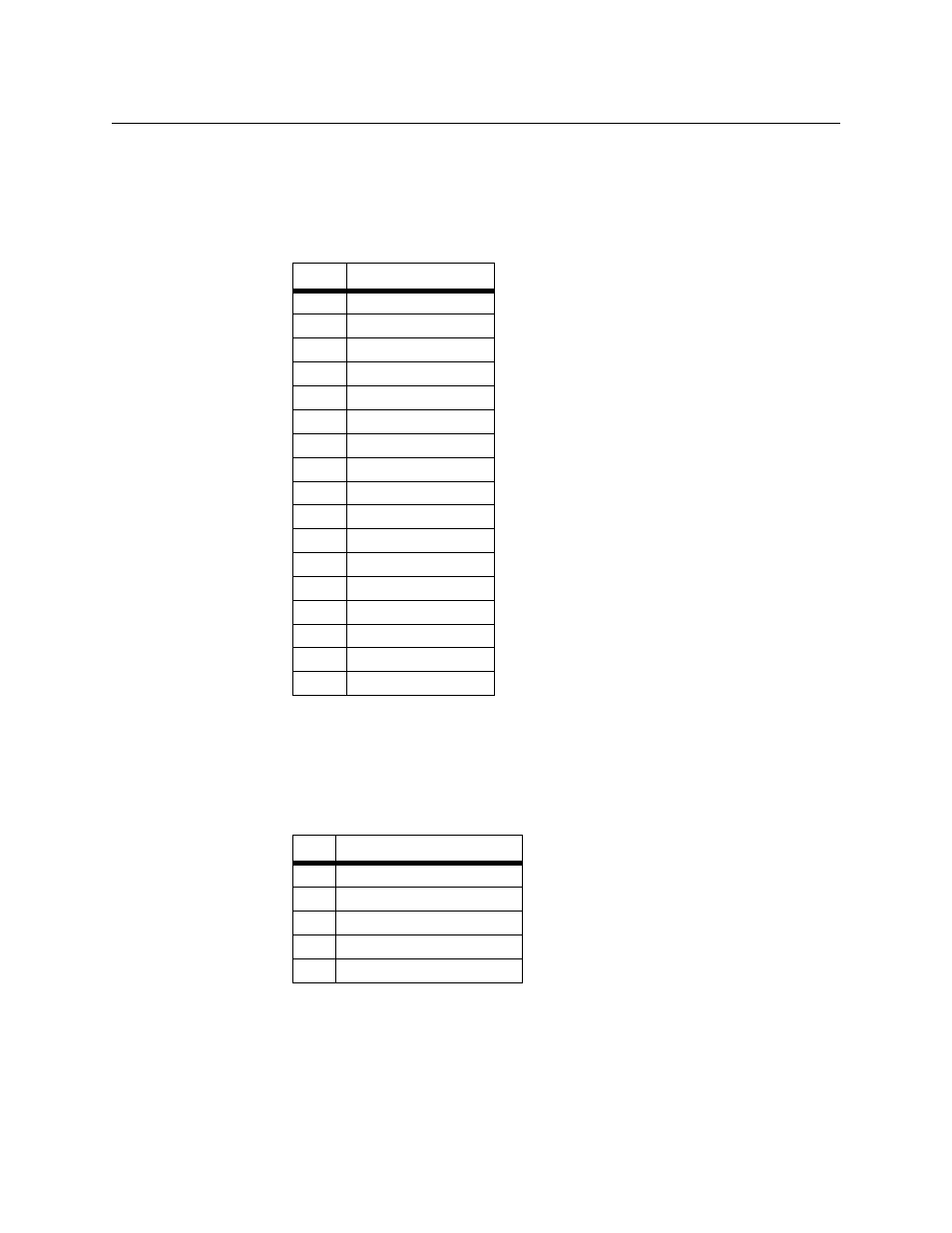
Table 2.1 shows the pinout for the V.35 data port. The form factor is a female
34-pin Winchester-type connector.
DDS CSU/DSU Network Port
Table 2.2 shows the pinout for the network connector. The connector interface
is RJ-48S.
T1 CSU/DSU and FrameStart FSE Network Connection
The network side of the unit is referred to as the network interface. This
interface contains an ALBO (automatic line build out) that allows the unit to
be located a substantial distance away from the telco network interface with a
Table 2.1
Customer Equipment Connector Pinout
Pin
Signal
A
Frame Ground
B
Signal Ground
C
Request to Send
D
Clear to Send
E
Data Set Ready
F
Data Carrier Detect
H
Data Term Ready
P
Transmit Data (A)
R
Receive Data (A)
S
Transmit Data (B)
T
Receive Data (B)
U
Terminal Timing (A)
V
Receive Clock (A)
W
Terminal Timing (B)
X
Receive Clock (B)
Y
Transmit Clock (A)
AA
Transmit Clock (B)
Table 2.2
Network Connector Pinout
Pin
Signal
1
R (output to network)
2
T (output to network)
3–6 not used
7
T1 (input from network)
8
R1 (input from network)