Connecting the velocitykvm extender, Cooling, Front panel display and buttons – Thinklogical Velocitykvm-4, 5, 8, 24, 28, 34, 35 & 38 Manual User Manual
Page 17
V e l o c i t y K V M E x t e n d e r P r o d u c t M a n u a l , R e v . B , J a n u a r y , 2 0 1 4
Page 17
Cooling
The VelocityKVM Extender System uses two DC fans to move air horizontally through the enclosure.
Note: Be sure to leave a minimum of 2” ventilation space on both sides of the units,
especially if the units are being stacked.
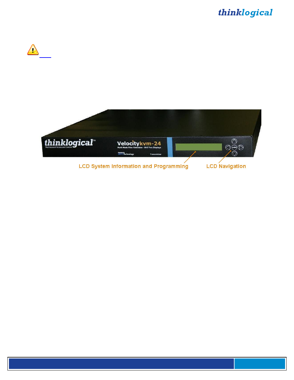
Front Panel Display and Buttons
The front-panel LCD display should be visible and accessible for system setup. The front panel buttons
are used to configure special video settings and to review existing VelocityKVM Extender configurations.
More detailed information on the Front Panel can be found in the General Front Panel Usage section
(Page 27).
VelocityKVM-24 Extender Front Panel LCD Display
Connecting the VelocityKVM Extender
Types of Connections
All physical connections to the product use industry-standard connectors. Non-supplied cables that may
be needed are commercially available. All connections are found on the rear of the unit.
Fiber Cable
Fiber-optic cables run between the Transmitter unit (near your CPU) and the Receiver unit (near your
desktop devices). The standard multi-mode fiber optic cables must be 50 or 62.5µm, terminated with LC,
ST or SC- type fiber optic connectors. Single-mode fiber optic cables must be 9µm, UPC (Ultra Physical
Contact), terminated with LC, ST or SC- type fiber optic connectors. Be careful not
to
kink or pinch the
fiber optic cable as it is being installed and keep all bend radii to no less than 3 inches (76.2mm).
It is the standard VelocityKVM convention that fiber L1 carries data (PS2, USB, audio, serial, etc.) and
video signal 1 (DVI or RGB) from the transmitter to the receiver. If a back channel is required, fiber L2
carries data from the receiver to the transmitter. If additional video channels are required, they are
carried from transmitter to receiver via fibers L3, L4 and L5, depending on the extender model. (See
page 53 for additional fiber configurations used with the Fail-Over option.)
Transmitter
The transmitter unit connects to the computer at the DVI In port using a DVI-D male-to-male cable
(CBL000009-002MR for single-link and/or CBL000023-002MR for dual-link) which is supplied with the
system. The connections to the VelocityKVM Extender Transmitters can be viewed in detail in the REAR
PANEL VIEW section of this manual beginning on page 19.
Receiver
The receiver unit connects to a video monitor using a DVI-D male-to-male cable. Peripherals connect
with their own standard cables. The connections to the VelocityKVM Extender Receivers can be viewed
in detail in the REAR PANEL VIEW section of this manual.