Sundance SMT702 User Manual
Page 47
0
0
Normal Operation
1
1
All register set to the default values
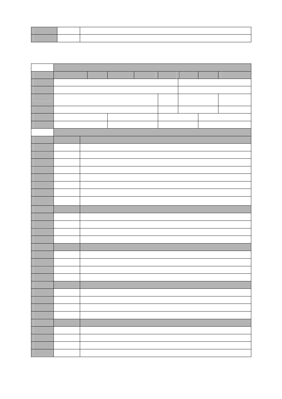
4.3.1.2.24
Frequency Synthesizer (LMX2531) Register R6 – 0xD8
(write and read).
Offset 0x0400 -
Frequency Synthesizer (LMX2531) Register R6 – 0xD8 (write and read)
Byte
Bit 7
Bit 6
Bit 5
Bit 4
Bit 3
Bit 2
Bit 1
Bit 0
2
Reserved
XTLSEL[2:0]
Default
‘00000’
‘000’
1
VCO_ACI_SEL[3:0]
EN_LPF
LTR
R4_ADJ[1:0]
R4_ADJ_FL[1:0
]
Default
‘0000’
‘0’
‘00’
‘00’
0
R4_ADJ_FL[1:0]
R3_ADJ[1:0]
R3_ADJ_FL[1:0]
C3_4_ADJ[2:0]
Default
‘00’
‘00’
‘00’
‘000’
Offset 0x0400 -
Frequency Synthesizer (LMX2531) Register R6 – 0xD8 (write and read)
Setting
Bit 2-0
Value for C3 and C4 in the internal loop filter – C3_4_ADJ[2:0]
0
0x0
C3=50pF and C4=50pF
1
0x1
C3=50pF and C4=100pF
2
0x2
C3=50pF and C4=150pF
3
0x3
C3=100pF and C4=50pF
4
0x4
C3=150pF and C4=50pF
5
0x5
C3=100pF and C4=100pF
6
0x6
C3=50pF and C4=150pF
7
0x7
C3=50pF and C4=150pF
Setting
Bit 4-3
Value for internal loop filter resistor R3 during fastlock – R3_ADJ_FL[1:0]
0
0x0
10 kΩ
1
0x1
20 kΩ
2
0x2
30 kΩ
3
0x3
40 kΩ
Setting
Bit 6-5
Value for internal loop filter resistor R3 – R3_ADJ[1:0]
0
0x0
10 kΩ
1
0x1
20 kΩ
2
0x2
30 kΩ
3
0x3
40 kΩ
Setting
Bit 8-7
Value for internal loop filter resistor R4 during fastlock – R3_ADJ_FL[1:0]
0
0x0
10 kΩ
1
0x1
20 kΩ
2
0x2
30 kΩ
3
0x3
40 kΩ
Setting
Bit 10-9
Value for internal loop filter resistor R4 – R4_ADJ[1:0]
0
0x0
10 kΩ
1
0x1
20 kΩ
2
0x2
30 kΩ
3
0x3
40 kΩ