Troubleshooting guide, Solenoid screen filter cleaning, Install cover and front panel(s) – Sloan EW-72000 Installaton User Manual
Page 7
Troubleshooting Guide
1. No water flows when sensor is activated
Ensure that main power supply is turned “ON.” Check receptacle,
transformer, solenoid, leads and connections.
If Sensor LED does not blink:
A.
Control module circuit board is faulty; replace.
B.
Sensor is faulty; replace sensor module.
If Sensor LED blinks when user is sensed:
A.
Supply Stop(s) may be closed; open Supply Stop(s).
B.
Debris may be in Solenoid filter; remove, clean and reinstall.
2. Very low flow or slow dribble
A.
Supply Stop(s) may be closed; open Supply Stop(s).
B.
Debris is in solenoid, won’t close properly; remove operator
and clean. Reassemble in the same manner.
C.
Debris is in Solenoid filter; remove, clean and reinstall.
D.
Debris is in spray head; remove, clean and reinstall.
3. Continues to run (even after power to faucet has been
disconnected)
A.
Solenoid valve is installed backwards; install correctly.
B.
Debris is in solenoid, won’t close properly; remove operator
and clean. Reassemble in the same manner.
7
Solenoid Screen Filter Cleaning
A
Before cleaning the Screen Filter, turn off the water supply at
supply stop(s).
B
Activate the Spray Head to relieve any pressure in the system.
D
Unscrew the Filter Cap and remove it from the Solenoid Valve
Housing.
E
Carefully remove the Screen Filter from the Solenoid Valve
Housing.
F
Clean the Screen Filter using fresh tap water only. If necessary,
use a small brush to clean. Use caution while cleaning to
prevent damage to Screen Filter.
G
Examine the Copper Washer for wear or damage; replace if
necessary. Carefully replace the Screen Filter into the Filter Cap.
Screw the Filter Cap with Copper Washer into the Solenoid
Valve Housing and tighten securely to prevent leaks.
H
Turn on the water supply at the supply stop(s). Activate the
Spray Head to purge any air from the system lines. Check for
leaks and repair as necessary.
C
Remove Cover as instructed in Step 6.
I
Install Cover as instructed in Step 12.
12
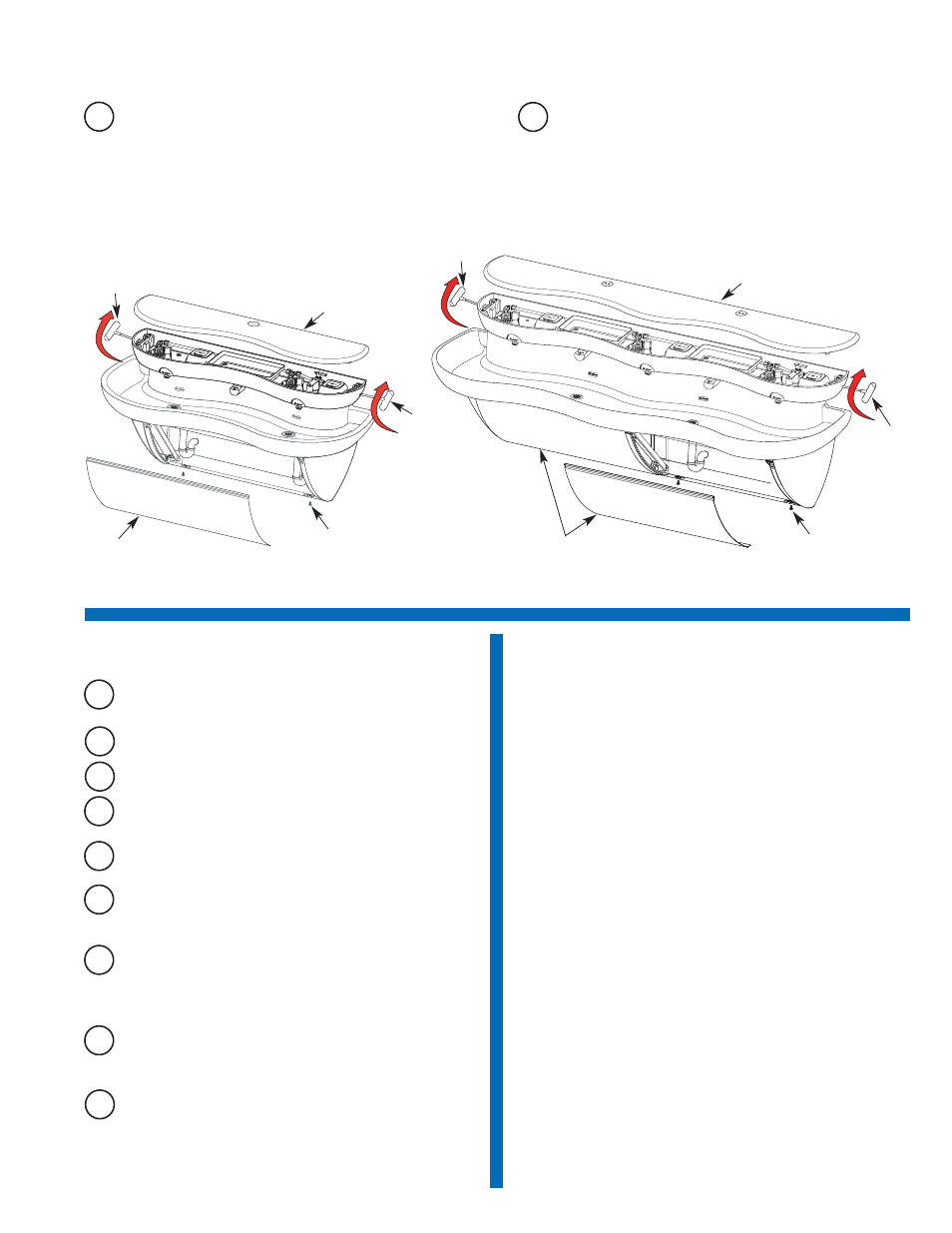
Install Cover and Front Panel(s)
A
Replace Cover and latch firmly in place with T-Handled Wrench
(Rotate top of handle toward wall until latch snaps into
position).
B
Replace Front Panel(s) by hanging top lip of Panel into track of
Trim Rail under Basin. Swing panel into position and affix with 2
Fasteners. Triple Station Models — repeat this procedure for
second panel.
Front Panel
Cover
T-Handle
Wrench
T-Handle
Wrench
Fastener (2)
Triple Station
Double Station
Front Panel (2)
Cover
T-Handle
Wrench
Fastener (4)
T-Handle
Wrench