Sloan 140 Royal / Regal Standard Concealed Flushometer User Manual
Page 4
4
A
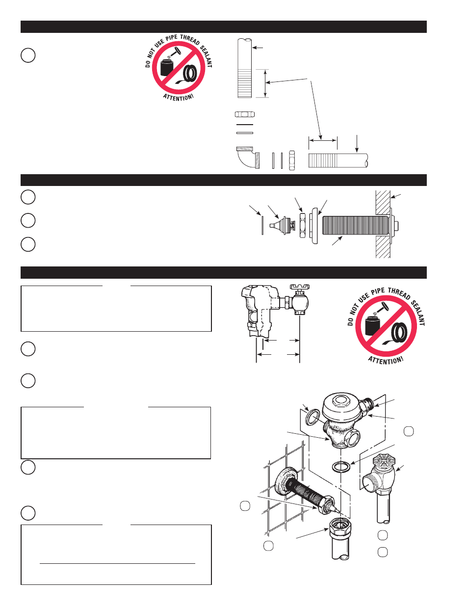
Assemble Pipe, Elbows, Couplings,
Nylon Slip Gaskets, Rubber Gaskets
and Flanges as illustrated on back
page. Hand tighten all Couplings.
IMPORTANT: WHEN CUTTING SCORED
PIPE TO FIT, LEAVE A MINIMUM
OF 1-1/4” (32 mm) OF SCORING TO
ENSURE PROPER ENGAGEMENT WITH
COMPRESSION COUPLINGS.
VACUUM
BREAKER
FLUSH
CONNECTION
Remove Actuator Shaft End, Coupling and Mounting Nut from
Actuator Assembly.
A
Insert Shaft of Actuator Assembly through the 1-1/2” (38 mm) wall
opening from fixture side of wall.
B
Install Mounting Nut, Coupling and Actuator Shaft End to Actuator
Assembly. Hand tighten Mounting Nut to wall. Securely tighten
Actuator Shaft End to Actuator assembly.
C
A-31
GASKET
ACTUATOR
SHAFT END
COUPLING
MOUNTING
NUT
ACTUATOR
ASSEMBLY
B
Align Flushometer directly above the Vacuum Breaker Flush
Connection. Assemble Vacuum Breaker Flush Connection to
Flushometer. Tighten Vacuum Breaker Coupling by hand.
A
Lubricate tailpiece O-ring with water. Insert Adjustable Tailpiece
into Control Stop while mounting Flushometer to Actuator
Assembly. Tighten Actuator and Tailpiece Couplings by hand.
MAXIMUM ADJUSTMENT OF THE SLOAN ADJUSTABLE TAILPIECE
IS 1/2” (13 MM) IN OR OUT FROM THE STANDARD
4-3/4” (121 MM) (CENTERLINE OF FLUSHOMETER
TO CENTERLINE OF CONTROL STOP).
IF ROUGHING-IN MEASUREMENT EXCEEDS 5-1/4” (133 MM),
CONSULT FACTORY FOR LONGER TAILPIECE.
NOTE
C
Use a wrench to tighten the following couplings in the order shown.
Align Flushometer Body and securely tighten first the Tailpiece
Coupling (1), then the Actuator Coupling (2), then the Vacuum
Breaker Coupling (3), then all Flush Connection Couplings (4) and
finally the Spud Coupling (5).
5-1/4”
(133 mm)
MAX.
4-1/4”
(108 mm)
MAX.
A-31
GASKET
ADJUSTABLE
TAILPIECE
TAILPIECE
COUPLING
G-44 GASKET
CONTROL
STOP
VACUUM
BREAKER
COUPLING
ACTUATOR
ASSEMBLY
COUPLING
FLUSHOMETER
BODY
D
Using a wrench, securely tighten Actuator Mounting Nut to wall.
1
5
4
3
2
FLUSH
CONNECTION
COUPLINGS
SPUD COUPLING
2 - INSTALL VACUUM BREAKER FLUSH CONNECTION
4 - INSTALL FLUSHOMETER
3 - MOUNT ACTUATOR ASSEMBLY TO WALL
USE A SLOAN A-50 “SUPER-WRENCH™”, SLOAN A-109
PLIER WRENCH OR SMOOTH JAWED SPUD WRENCH
TO SECURE ALL COUPLINGS. THIS WILL ELIMINATE
DAMAGE TO CHROME OR SPECIAL FINISH THAT
NORMALLY OCCURS WHEN SLIP-JOINT PLIERS, PIPE
WRENCHES OR OTHER “TOOTHED” TOOLS ARE USED.
!!! IMPORTANT !!!
WALL
(FIXTURE
SIDE)
For high efficiency urinal flushometers (0.5, 0.25 and 0.125 gpf),
it is necessary to first insert the flow control component into the
tailpiece assembly. See the H1015A flow control kit and separate
instructions for details on how to install.
NOTE