RGBLink New Driver 2 Quick Start User Manual
Page 21
Address:S602-604 Weiye Building Torch Hi-Tech Industrial Development Zone Xiamen,Fujian Province, P.R.C
Tel: 00865925771197 Fax:00865925771202
Email: [email protected] http://www.rgblink.cn
20
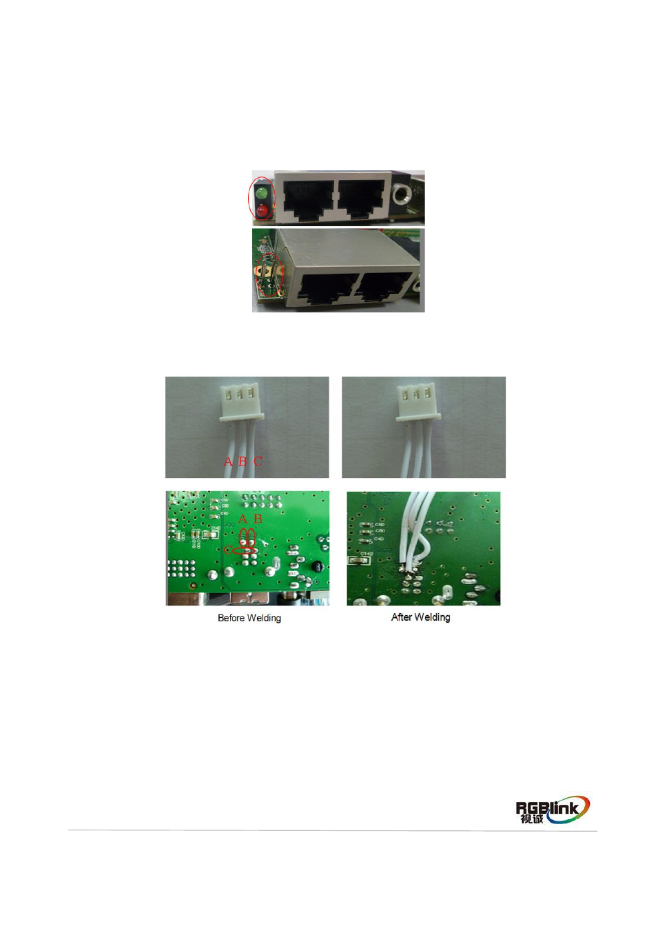
Sending Card Panel Installation
Please process the sending card panel before install the sending card. Operations are as follows:
1. Take a piece of sending card, and remove the stand of the LEDs, weld on a 2*2 pin, 2.54 mm pitch
row needle, as shown below (applicable to LINSN, Colorlight T7 and Nova sending card).
2. Take another sending card and a 3P double line (30 cm long, 2.54 pitch), cut one side of the stand,
and weld to the back of sending card, as shown in the figure below:
Note: Step 2 is only applicable for Linsn sending card.
Linsn Sending Card Panel Installation
1. Lock Linsn sending card by 6 screws P (3*5), as shown in the below red circle, and by two screws
(3*6) with a flat pad screws power ground, as shown in the blue box shown in the diagram below. Then
take a terminal line (
φ 4.0 round head terminal, +5 mm immersion, 1015-18 #/, yellow green double
color line, 170 mm long), weld one end of the subline to the stand on network interface of sending card: