RGBLink New Driver User Manual User Manual
Page 49
New Driver User Manual 49
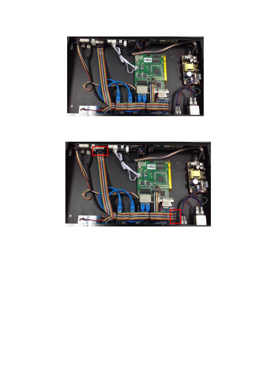
5. Connect (NEW DRIVER 2)-MCU board to (NEW DRIVER 2)-CON board with
2*8IDC line. Please refer to the following figure for more detailed connections:
6. Dispensing on each screw, and heat glue on each connection joints.
7. Finishing and binding the cables
.
8. After it has been confirmed correct, cover the front panel, and fixed by 6 pieces of
3*5 black flat head screws, as shown in the figure below:
This manual is related to the following products:
See also other documents in the category RGBLink Equipment:
- Driver 2A Quick Start (2 pages)
- VSP 112U (15 pages)
- VSP 112U (108 pages)
- VENUS X1 Quick Start (19 pages)
- Driver User Manual (44 pages)
- New Driver Quick Start (22 pages)
- MVP 320 Quick Start (2 pages)
- New Driver 2 Quick Start (27 pages)
- MSP 215A (6 pages)
- MSP 204 Quick Start (2 pages)
- MVP 320 User Manual (60 pages)
- VENUS X1 User Manual (135 pages)
- MSP 203 User Manual (37 pages)
- VENUS X3 Quick Start (37 pages)
- VSP 628PRO Quick Start (32 pages)
- VSP 168HD Quick Start (19 pages)
- VSP 168HD User Manual (100 pages)
- VSP 628PRO User Manual (120 pages)
- VENUS X2 Quick Start (31 pages)
- VSP 3550S Quick Start (4 pages)
- VSP 5162PRO (114 pages)
- VSP 5162PRO (18 pages)
- DV4 Quick Start (2 pages)
- VENUS X2 User Manual (68 pages)
- DV4 User Manual (31 pages)
- Driver Quick Start (17 pages)
- VSP 3550S User Manual (88 pages)
- Driver 4 Quick Start (2 pages)
- TSH4 Quick Start (1 page)
- VSP 5360 (16 pages)
- VSP 5360 (110 pages)
- TSH4 User Manual (31 pages)
- CP 3096 Quick Start (18 pages)
- CP 2048 (5 pages)
- DXP A1616 Quick Start (3 pages)
- CP 3072 Quick Start (18 pages)
- DXP D1616 Quick Start (13 pages)
- DXP D0404 Quick Start (1 page)
- DXP A1616 User Manual (50 pages)
- DXP D0108 Quick Start (1 page)
- CP 3072 User Manual (75 pages)
- DXP D0404 User Manual (30 pages)
- DXP D0108 User Manual (31 pages)
- DXP D1616 User Manual (76 pages)