RGBLink New Driver User Manual User Manual
Page 48
New Driver User Manual 48
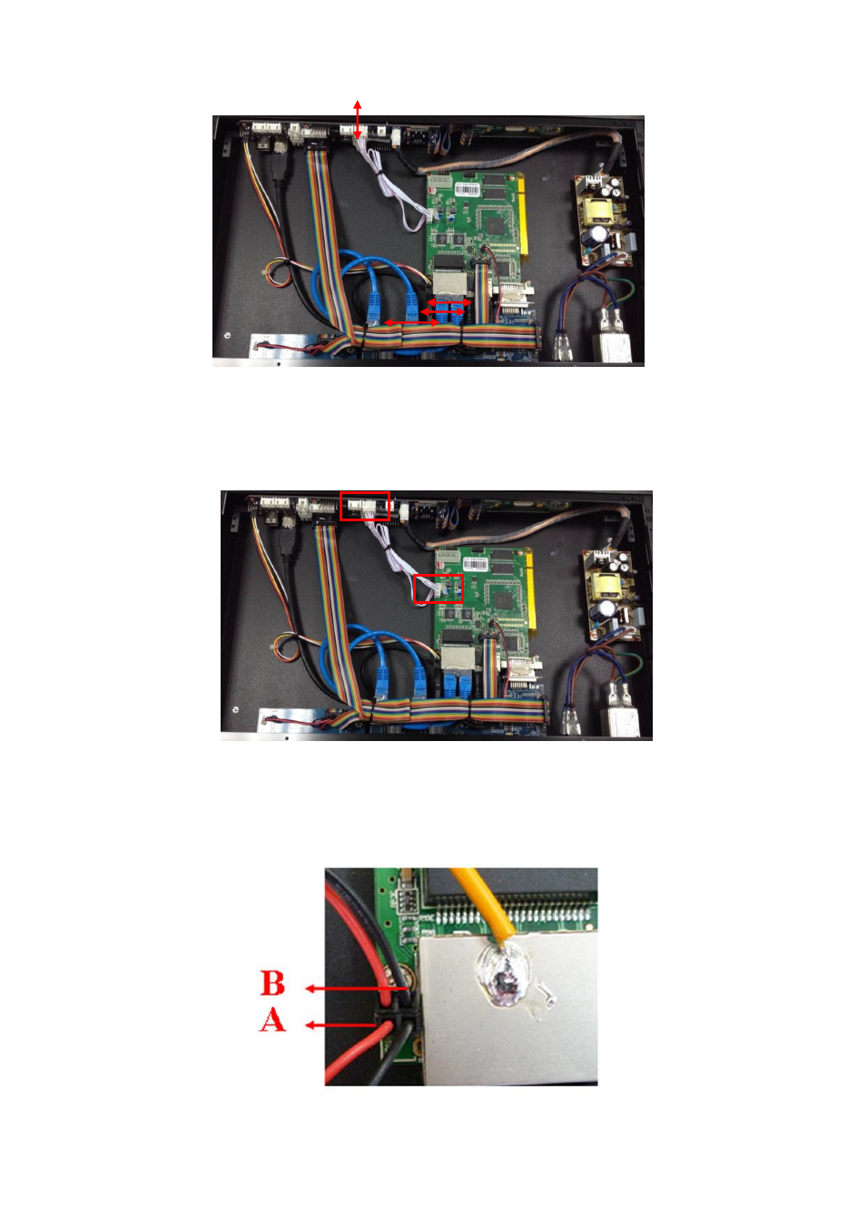
3. Connect the power line of sending card, (connect to the position marked LINSN
POW of the MCU board), take a 4 pin 2.54 mm pitch cable, and connect referring to
the following figure:
4. Connect the signal and power indicator light cable of sending card, take each 2 red
and black lines, and connect 2 black lines to the end of MCU board (Part B), and connect
2 red lines near the edge of the MCU board (Part A). Please refer to the following figure:
This manual is related to the following products:
See also other documents in the category RGBLink Equipment:
- Driver 2A Quick Start (2 pages)
- VSP 112U (15 pages)
- VSP 112U (108 pages)
- VENUS X1 Quick Start (19 pages)
- Driver User Manual (44 pages)
- New Driver Quick Start (22 pages)
- MVP 320 Quick Start (2 pages)
- New Driver 2 Quick Start (27 pages)
- MSP 215A (6 pages)
- MSP 204 Quick Start (2 pages)
- MVP 320 User Manual (60 pages)
- VENUS X1 User Manual (135 pages)
- MSP 203 User Manual (37 pages)
- VENUS X3 Quick Start (37 pages)
- VSP 628PRO Quick Start (32 pages)
- VSP 168HD Quick Start (19 pages)
- VSP 168HD User Manual (100 pages)
- VSP 628PRO User Manual (120 pages)
- VENUS X2 Quick Start (31 pages)
- VSP 3550S Quick Start (4 pages)
- VSP 5162PRO (114 pages)
- VSP 5162PRO (18 pages)
- DV4 Quick Start (2 pages)
- VENUS X2 User Manual (68 pages)
- DV4 User Manual (31 pages)
- Driver Quick Start (17 pages)
- VSP 3550S User Manual (88 pages)
- Driver 4 Quick Start (2 pages)
- TSH4 Quick Start (1 page)
- VSP 5360 (16 pages)
- VSP 5360 (110 pages)
- TSH4 User Manual (31 pages)
- CP 3096 Quick Start (18 pages)
- CP 2048 (5 pages)
- DXP A1616 Quick Start (3 pages)
- CP 3072 Quick Start (18 pages)
- DXP D1616 Quick Start (13 pages)
- DXP D0404 Quick Start (1 page)
- DXP A1616 User Manual (50 pages)
- DXP D0108 Quick Start (1 page)
- CP 3072 User Manual (75 pages)
- DXP D0404 User Manual (30 pages)
- DXP D0108 User Manual (31 pages)
- DXP D1616 User Manual (76 pages)