New driver back panel, Dial switch, 3: rs232 control port – RGBLink New Driver User Manual User Manual
Page 23: Hardware orientation
2. Hardware Orientation
New Driver Back Panel
New Driver User Manual 23
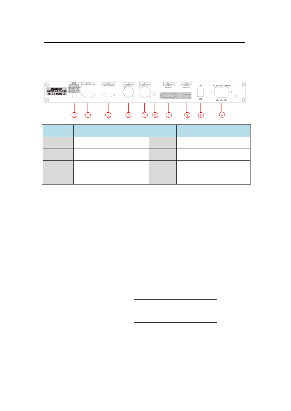
The figure below illustrates the professional interface and control signals
of New Driver back panel:
1: Dial Switch
Dial switch 1 and dial switch 2 upward: Operation for the first controller.
Dial switch 1 downward and dial switch 2 upward: Operation for the
second controller.
Dial switch 1 upward and dial switch 2 downward: Operation for the
third controller.
Dial switch 1 and dial switch 2 downward: Operation for the fourth
controller.
Note
Dial switch operation only when
cascade, and cascade is only
available for Linsn sending card.
2. 3: RS232 Control Port
2: OUTPUT is serial female port.
3: INPUT is serial male port.
NO
INTERFACE
NO
INTERFACE
1
Cascade Dial Switch
7
DVI Input
2. 3
RS232 Control Port
8
HDMI Input
4. 5
Cable Output of Sending Card
9
Switch
6
Audio Input
10
Power