1 wiring diagrams, Wiring diagrams – Research Concepts RC2500 User Manual
Page 123
116
RC2500 Antenna Controller
Appendix K
Driving 36VDC Motors
Research Concepts, Inc. • 5420 Martindale Road • Shawnee, Kansas • 66218-9680 • USA
www.researchconcepts.com
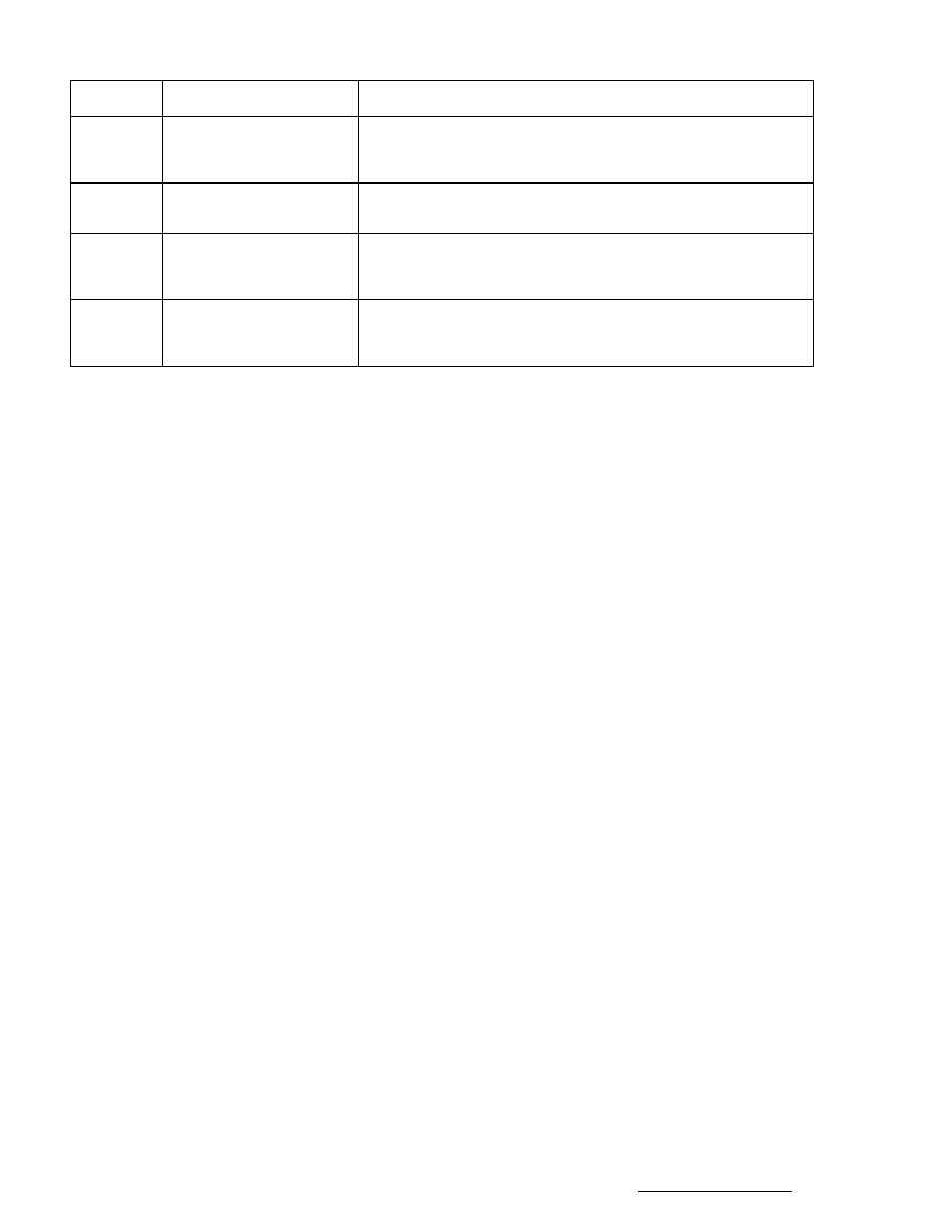
Terminal
Signal Name
Description
9
DRIVE COMMON
This terminal is internally connected to the DRIVE COMMON
terminals found on the Antenna I/O connector (J7). In this
design this terminal is tied to ground.
13
GROUND
This terminal is tied to the ground return of the controller’s 24
VDC unregulated power supply.
16
AZ CCW LIMIT
This terminal is internally connected to the SUMMARY LIMIT
input terminal found on the Antenna I/O connector (J6). In this
design this terminal is tied to 24 VDC.
25
24 VDC
This terminal is tied to the controller’s unregulated 24 volt DC
power supply. This AIU interface is powered by the controller’s
unregulated supply.
3.1
Wiring Diagrams
Two wiring diagrams describe the interface of the RC2500 to the AIU. All of the wiring can be performed
using the two 25 pin D connectors – no external terminal strips are needed. The drawing labeled
‘RC2500 Wiring Diagram’ show the connections between the AIU and RC2500. The drawing labeled
‘RC2500 Auxiliary I/O Connector’ describes the required connections on the J6 connector.