Vcm controller technical guide 9, Figure 5: vcm controller w iring diagram, All comm loop wiring is s traight thru – Orion System VCM Controller User Manual
Page 9: Tto t , r to r & shld to shld
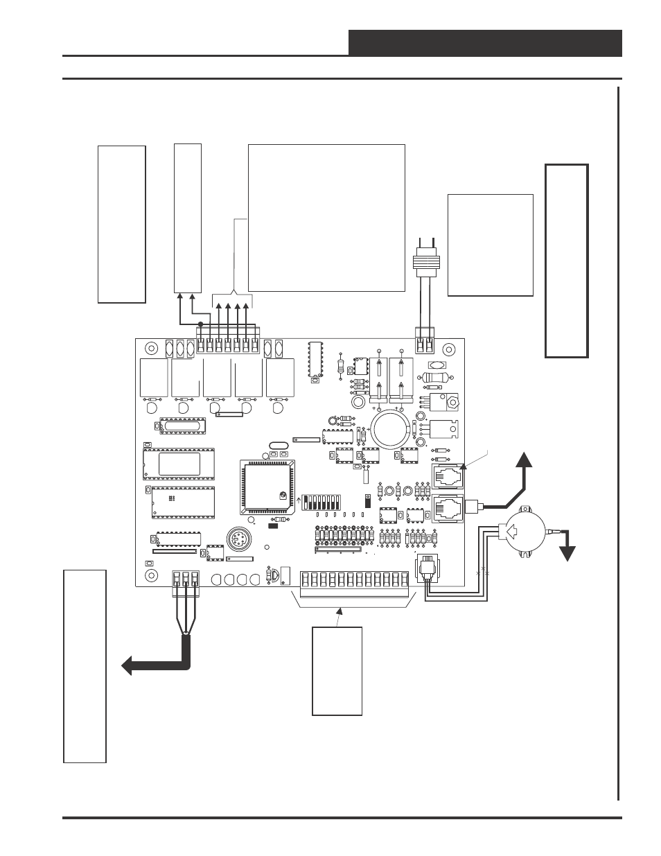
VCM Controller
Technical Guide
9
Line
V
olt
age
All
Comm
Loop
Wiring
Is
S
traight
Thru
24V
AC
GND
Local
Loop
RS-485
9600
Baud
See
Individual
Component
Wiring
Diagrams
For
Det
ailed
Wiring
Of
Analog
Input
s
And
Output
s
For
S
tand
Alone
Applications,
Connect
T
o
System
Manager
.
For
Network
Applications
Connect
T
o
Next
Controller
And/Or
MiniLink
PD
On
Local
Loop.
G
-
Fan
ON/OFF
Only
R
-
24V
AC
Relay
Output
Dry
Cont
act
s
R2
Thru
R5
May
B
e
U
ser
Configured
For
The
Following:
1
-
H
eating
S
tages
2
-
C
ooling
S
tages
3
-
W
arm-up
Mode
Command
(V
A
V
B
oxes)
4
-
R
eversing
V
alve
(Air
T
o
Air
H
eat
Pump
s)
5
-
R
eheat
Control
(Dehumidification)
6
-
E
xhaust
Fan
Interlock
7
-
P
reheater
For
L
ow
Ambient
Protection
8
-
Alarm
9
-
O
verride
10
-
O
ccupied
1
1-O
A
D
a
m
p
e
r
Note:
A
T
ot
al
Of
20
Relays
Are
A
vailable
By
Adding
Relay
Exp
ansion
B
oards.
All
E
xp
ansion
Board
Relay
Output
s
Are
User
Configurable
As
Listed
A
bove.
Connect
FRP
T
ubing
T
o
High
Pressure
Port
(Bottom
T
ube)
and
Route
T
o
S
tatic
Pressure
Pickup
Probe
Located
In
Unit
Discharge.
Leave
Port
Marked
“Lo”
Open
T
o
Atmosphere
OE271
S.P
.
T
ransducer
S
plice
If
Req’d
Connect
T
o
Exp
ansion
Board
Base
(When
Used)
Connection
Port
For
DigiSensor
RLY1
D1
D2
D3
D4
D5
RAM
C3
C2
U6
PHILIPS
CX6
C1
CX2
U2
PA
L
CX4
U4
TUC-5R
PLUS
YS101816
REV
.
2
V1
V2
V3
V5
V4
TB2
4
NETWORK
T
OKEN
16
32
8
SW1
ADD
2
1
ADDRESS
V6
POWER
GND
24V
AC
L1
D16
R6
C9
SC1
R11
U11
MC34064A
D13
C16
9936
VR2
TB4
R27
C13
R10
VR1
C19
C18
NE5090NPB3192 0PS
U8
CX8
U9
X1
R7
D10
R13
D12
C7
CX10
U10
CX12
U12
U14
CX14
PJ3
PJ2
PJ1
EXP
ANSION
PRESSURE
SENSOR
C17
D15
R26
C20
R25
R24
R22
U15
CX13
U13
C15
R19
R15
C14
D18
D17
PU1
PU2
PU3
PU4
PU5
PU7
D6
D7
D8
D9
D1
1
D14
C12
C10
0-5
VDC
0-1
VDC
JP1
C11
X2
GND
TB3
INPUTS
GND
GND
+VDC
AIN1
AIN2
AIN3
AIN4
AIN5
AOUT1
AOUT2
AIN7
RN4
1
RN5
RS-485
CX5
U5
R
TB1
SHLD
T
COMM
COMM
RN3
1
RN1
U1
CX1
1
LD6
COMM
PWR
LD7
LED1
LED2
LD9
LD8
R1
U7
RV
1
VREF
ADJ
R28
+VREF
5.1
1
V
TEST
POINT
EWDOG
D19
RN2
1
COM1-3
COM4-5
R5
R4
R3
R2
R1
RLY2
RLY3
RLY4
RLY5
CX15
(1
MEG)
HH
P1
C21
CX3
EPROM
U3
W
arning:
24
V
A
C
M
ust
Be
Connected
So
That
All
G
round
W
ires
Remain
Common.
Failure
T
o
Do
So
W
ill
Result
In
Damage
T
o
The
Controllers.
T
to
T
,
R
to
R
&
SHLD
to
SHLD
Size
T
ransformer
For
Correct
T
o
ta
l
Load.
VCM
Controlle
r=8V
A
Power
Consumption.
If
Economizer
Option
Is
Used
The
Economizer
Actuator
V
A
load
Must
Also
Be
Considered
When
Sizing
The
T
ransformer
.
OE331-21-VCM
VCM
Controller
Board
Note:
All
Relay
Output
s
Are
Normally
Open
And
Rated
For
24
V
A
C
Power
Only
.
2
Amp
Maximum
Load.
Figure 5: VCM Controller W
iring Diagram