Controller installation & wiring, Technical guide vcm controller 10, General – Orion System VCM Controller User Manual
Page 10: Controller mounting, Important wiring considerations
Technical Guide
VCM Controller
10
Controller Installation & Wiring
General
Correct wiring of the VCM controller is the most important factor in
the overall success of the controller installation process. In general most
VCM controllers are factory installed and wired at the AAON
®
factory.
It is also possible to purchase these controllers directly from WattMaster
Controls for installation in the field. Some of the following information
pertains to field wiring and may not apply to your installation since it
was pre-wired at the factory. However, in the unlikely event that trouble-
shooting of the controller is required, it is a good idea to be familiar
with the system wiring, no matter if it was factory or field wired.
Controller Mounting
When the controller is to be field mounted, it is important to mount the
controller in a location that is free from extreme high or low tempera-
tures, moisture dust and dirt. See Table 1 for a list of the required oper-
ating conditions for the VCM Controller and associated expansion
boards.
Be careful not to damage the electronic components when mounting
the controller. Remove the controller from its backplate. Mark the con-
trol enclosure base using the backplate as a template. Drill pilot holes in
the enclosure base and secure the backplate to it using sheet metal screws.
Do not allow metal shavings to fall onto the circuit board. Reattach the
controller to the backplate.
Important Wiring Considerations
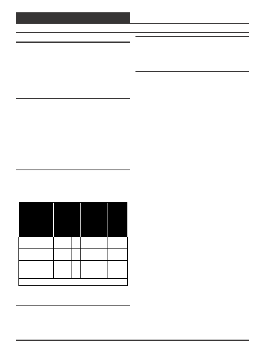
The VCM controller and expansion boards must be connected to a 24
VAC power source of the proper size for the calculated VA load re-
quirements. All transformer sizing should be based on the VA rating
listed in Table 1.
Control
Device
V
oltage
VA
Load
O
perating
Tem
perature
O
perating
Hu
m
id
it
y
VCM Controller
Board
24VAC
60Hz
8
10
°
F to 149
°
F
90% RH
*N.C.
2 Slot Expansion
Base Board
24VAC
60Hz
10
10
°
F to 149
°
F
90% RH
*N.C.
4 Slot Expansion
Base Board
24VAC
60Hz
20
10
°
F to 149
°
F
90% RH
*N.C.
* Non-Condensing
Table 1: Voltage and Environment Requirements
Warning: When using a single transformer to power more
than one controller or expansion board, the correct
polarity must always be maintained between the
boards. Failure to observe correct polarity will
result in damage to the VCM controller and
expansion boards.
Please carefully read and apply the following information when wiring
the VCM controller or the VCM Expansion Boards. See Figure 5 for
VCM controller wiring diagram. See Figures 6, 7 and 8 for Expansion
Board Wiring.
1.
All wiring is to be in accordance with local and national
electrical codes and specifications.
2.
Minimum wire size for 24 VAC wiring should be 18 gauge.
3.
Minimum wire size for all sensors should be 24 gauge.
Some sensors require 2 conductor wire and some require 3
or 4 conductor wire.
4.
Be sure that all wiring connections are properly inserted
and tightened into the terminal blocks. Do not allow wire
strands to stick out and touch adjoining terminals which
could potentially cause a short circuit.
5.
When communication wiring is to be used to interconnect
VCM controllers together or to connect to other
communication devices, all wiring must be plenum rated,
minimum 18 gauge, 2 conductor, twisted pair with shield.
WattMaster can supply communication wire that meets this
specification and is color coded for the network or local
loop. Please consult your WattMaster distributor for
information. If desired, Belden #82760 or equivalent wire
may also be used.
6.
Before applying power to the VCM controller, be sure
to recheck all wiring connections and terminations
thoroughly.