Appendix, Technical guide vcm controller 54, Oe265 rh sensor testing – Orion System VCM Controller User Manual
Page 54
Technical Guide
VCM Controller
54
Appendix
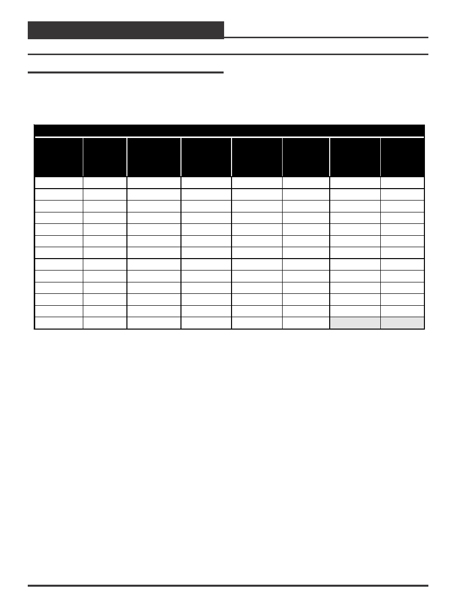
OE265-03 Relative Humidity Sensor
Testing Instructions:
Use the voltage column to check the Humidity Sensor while connected
to a powered expansion board. Read voltage with meter set on DC volts.
Place the “-”(minus) lead on terminal labeled GND and the “+” lead on
OE265 Relative Humidity Transmitters – Humidity vs. Voltage For 0-5 VDC Sensors
Humidity
Percentage
(RH)
Voltage
@
Input
(VDC)
Humidity
Percentage
(RH)
Voltage
@
Input
(VDC)
Humidity
Percentage
(RH)
Voltage
@
Input
(VDC)
Humidity
Percentage
(RH)
Voltage
@
Input
(VDC)
0%
0.00
26%
1.30
52%
2.60
78%
3.90
2%
0.10
28%
1.40
54%
2.70
80%
4.00
4%
0.20
30%
1.50
56%
2.80
82%
4.10
6%
0.30
32%
1.60
58%
2.90
84%
4.20
8%
0.40
34%
1.70
60%
3.00
86%
4.30
10%
0.50
36%
1.80
62%
3.10
88%
4.40
12%
0.60
38%
1.90
64%
3.20
90%
4.50
14%
0.70
40%
2.00
66%
3.30
92%
4.60
16%
0.80
42%
2.10
68%
3.40
94%
4.70
18%
0.90
44%
2.20
70%
3.50
96%
4.80
20%
1.00
46%
2.30
72%
3.60
98%
4.90
22%
1.10
48%
2.40
74%
3.70
100%
5.00
24%
1.20
50%
2.50
76%
3.80
the AIN terminal that the Humidity sensor is connected to on the Ana-
log Input/Output Expansion Board.
OE265 RH Sensor Testing
The chart below is used to troubleshoot the OE265 Relative Humidity
Sensors.