Expansion board installation & wiring, Technical guide vcm controller 12, Wiring considerations – Orion System VCM Controller User Manual
Page 12
Technical Guide
VCM Controller
12
Expansion Board Installation & Wiring
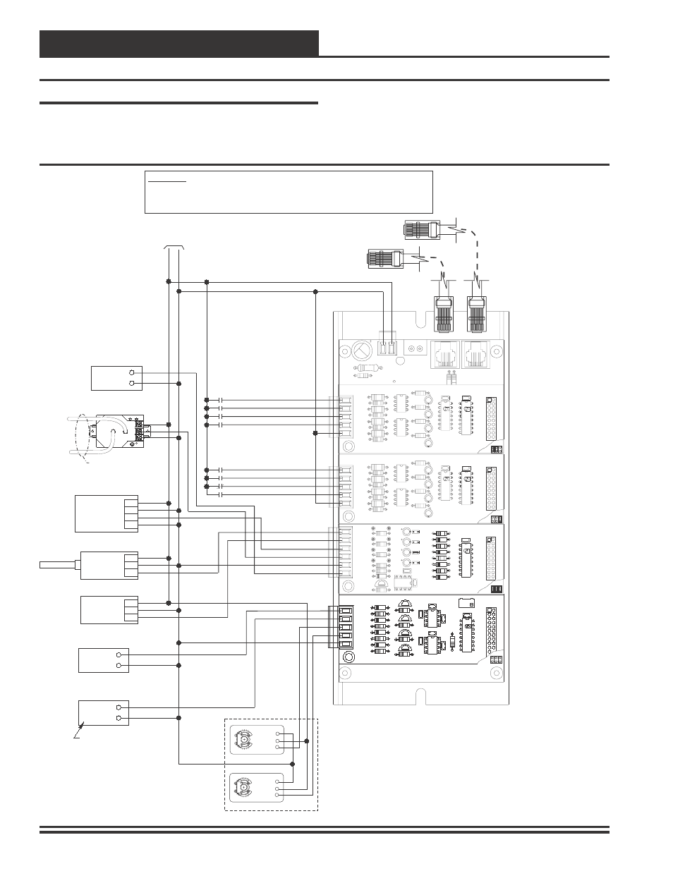
Figure 7: Expansion Board Wiring Details For Binary Input, Analog Input and Analog Output Boards
R20
C8
TB2
D3
PWR LD1
24V
AC-IN
GND
GND
TB1
PJ2
+24VDC-OUT
R17
PJ1
R15
R4
R3
R2
R1
YS101788
BIN 4
BIN 3
BIN 2
BIN 1
COM
TB1
OPTO2
R10
R12
4 DIG. IN MOD. I/O BD.
P2506-2
R8
R6
R5
P2506-2
OPTO1
74HC14N
PCF8574P
U2
C4
C3
U1
CX2
C2
C1
CX1
P1
R4
R3
R2
R1
YS101788
BIN 4
BIN 3
BIN 2
BIN 1
COM
TB1
OPTO2
R10
R12
4 DIG. IN MOD. I/O BD.
P2506-2
R8
R6
R5
P2506-2
OPTO1
74HC14N
PCF8574P
U2
C4
C3
U1
CX2
C2
C1
CX1
P1
OE356
-4
Binary
Input
Board
#
1
OE356
-4
Binary
Input
Board
#
2
OE355
-
4
Analog
Output
Board
Remote Forced Heating - N.O. Contact
Remote Forced Cooling - N.O. Contact
Hood On - N.O. Contact
Dirty Filter - N.O. Contact
Proof Of Flow - N.O. Contact
Remote Forced Occupied - N.O. Contact
+
COM
+
COM
VOUT (0-5V)
GND
VIN
VAC OR DC
GND
0-5V
0-10V OUTPUT
SIGNAL GROUND
+
-
AC/GND
AC+/DC+
LOW
HIGH
COM
COM
OUT
EXC
+
+
+
Smoke Detector - N.C. Contact
Remote Forced Dehumidification
N.O. Contact
AOUT2
AOUT4
GND
AOUT1
AOUT3
COM
BIN4
BIN3
BIN2
BIN1
COM
BIN3
BIN4
BIN1
BIN2
Plastic Tubing To Building
Pressure Sensing Locations
Building Pressure
Relief FAN VFD
Modular Cable
Connect To VCM Controller
Modular Cable
Connect To Next Expansion Board
(When Used)
24
V
A
C
GND
Orion - OE258 Building Pressure
Transducer
Orion - OE255 Room Mounted CO2 Sensor
Or
Orion - OE256 Return Air Mounted CO2 Sensor
Orion - OE265-13 Outdoor Air
Humidity Sensor
Orion OE265-11 Indoor Air
Humidity Sensor
Modulating Heating
(0 to 10 VDC Input)
Modulating Cooling
Or Digital Scroll Compressor
(1.5 to 5, 0 to 10 or 2 to 10 VDC Input)
Return Air Bypass
Damper Actuator
(0-10 VDC)
Return Air
Damper Actuator
(0-10 VDC)
Belimo Actuator Wiring
Shown. Consult Factory For
Other Manufacturers Wiring
Instructions
When Copeland Scroll Compressor Is
Used Wire Per Copeland Digital Scroll
Wiring Detail
OE352 2 Slot Or OE353 - 4 Slot Expansion Board
As Required - OE353 Is Shown
10 VA Minimum Power Required For
Each OE352 - 2 Slot Expansion Base Board.
20 VA Minimum Power Required For
Each OE353 - 4 Slot Expansion Base Board
WARNING!!
Observe Polarity! All boards must be wired with GND-to-GND and 24VAC-to-24VAC. Failure to observe
polarity will result in damage to one or more of the boards. Expansion Boards must be wired in such a way that
power to both the expansion boards and the controller are always powered together. Loss of power to the
expansion board will cause the controller to become inoperative until power is restored to the expansion board.
JO3
JO4
JO2
JO1
CX2
R10
AOUT1
AIN4
TB1
GND
AIN2
AIN3
AIN1
PU4
U2
D5
Q1
R8
R9
LM358
C5
C1
R7
R6
R5
PU3
C4
C3
C2
PU2
PU1
4 ANALOG IN MOD. I/O BD.
R3
YS101784
D4
R4
D3
D1
D2
R2
R1
CX1
U1
P1
OE354
-
4
Analog
Input
-
1
Analog
Output
Board
AIN3
AOUT1
GND
AIN4
AIN1
AIN2
GND
AOUT1
YS101786
4 AOUT MOD. I/O BD.
CX1
U1
Q1
LM358
R2
U2
R9
D1
R6
D2
R7
D4
D3
R8
TB1
CX2
C3
C1
P1
RV
1
R1
C4
U3
C2
LM358
CX3
AOUT2
AOUT3
AOUT4
Q2
R3
Q4
Q3
R4
R5
Y1
3
Y1
3
+
2
+
2
COM 1
COM 1
Wiring Considerations
The expansion base boards must be connected to 24 VAC as shown in
the wiring diagram below. Please see Table #1 for correct VA require-
ments to use when sizing the transformer(s) used for powering the ex-
pansion base boards.
Also please note that when wiring the OE356 - 4 Binary Input Expan-
sion Board(s), its contacts must be wired as wet contacts (connected to
24 VAC) not dry contacts as used with the OE357 - 4 Relay Expansion
Boards . See Figures 7 and 8 for complete wiring details.