Figure 24: building pressure control output wiring, Philips – Orion System VCM Controller User Manual
Page 27
VCM Controller
Technical Guide
27
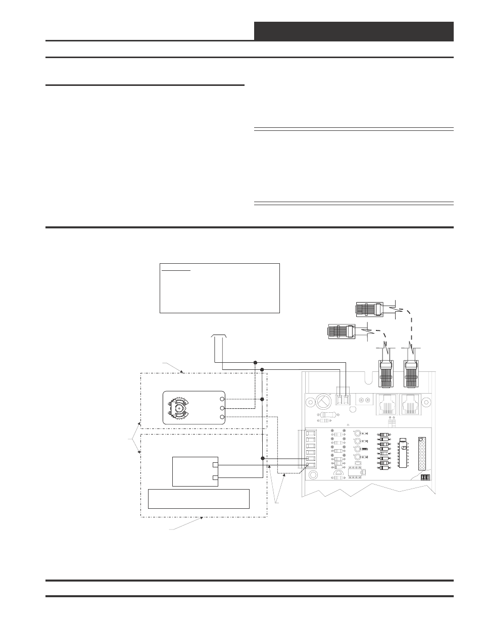
Building Pressure Control
Output Wiring
The Building Pressure Control Output is a 0-10 VDC or 2-10 VDC
signal sent from the OE354, 4 Analog Input 1 Analog Output Expan-
sion Board. When using the output for Direct Building Pressure control
(output signal rises on a rise in building pressure), the output signal can
be connected to either a Variable Frequency Drive controlling an ex-
haust fan or to a damper actuator controlling an exhaust damper. When
used in this manner the output signal must be configured for Direct
Acting operation.
When using this output for Reverse Building Pressure Control (output
signal rises on a fall in building pressure), a damper actuator control-
ling an OA Damper would be used. When using the OA damper for
Reverse Building Pressure Control, the output signal must be config-
ured for Reverse Acting operation. A Building Pressure Sensor con-
24
V
A
C
GND
10 VA Minimum Power Required For
Each 2 Slot Expansion Base Board.
20 VA Minimum Power Required For
Each 4 Slot Expansion Base Board
R20
C8
TB2
D3
PWR LD1
24V
AC-IN
GND
GND
TB1
PJ2
+24VDC-OUT
R17
PJ1
R15
Connect To VCM Controller
Connect To Next Expansion Base Board
(When Used)
OE354
-
4
Analog
Input
-
1
Analog
Output
Board
GND
AOUT1
JO3
JO4
JO2
JO1
CX2
R10
AOUT1
AIN4
TB1
GND
AIN2
AIN3
AIN1
PU4
U2
D5
Q1
R8
R9
LM358
C5
C1
R7
R6
R5
PU3
C4
C3
C2
PU2
PU1
4 ANALOG IN MOD. I/O BD.
R3
PCF8591P
YS101784
D4
R4
D3
D1
D2
R2
R1
PHILIPS
T L
HA
AN
I D
CX1
U1
P1
+
Building Pressure Control
Exhaust Fan Variable Frequency Drive
(By Others)
_
0-10VDC or 2-10 VDC
(Configurable)
GND
The VFD Unit Must Be Configured For 0-10vdc Input. The
Input Resistance At The VFD Must Not Be Less Than 1000
Ohms When Measured At The VFD Terminals With All
Input Wires Removed.
WARNING!!
Observe Polarity! All boards must be wired with GND-to-
GND and 24VAC-to-24VAC. Failure to observe polarity will
result in damage to one or more of the boards. Expansion
Boards must be wired in such a way that power to both the
expansion boards and the controller are always powered
together. Loss of power to the expansion board will cause
the controller to become inoperative until power is restored
to the expansion board.
OE352 or OE353 Expansion Base Board
Building Pressure Control
Damper Actuator
(By Others - Belimo Actuator Shown)
Wiring When Using Damper Actuator
For Building Pressure Control
Both Types Of Building Pressure Control
Devices Are Shown
Only One Type Of Building Pressure Control
Device May Be Used On Each HVAC Unit
Wiring When Using Exhaust Fan VFD
For Building Pressure Control
GND
24 VAC
Y1 3
Y1 3
+ 2
+ 2
COM -
1
COM -
1
Belimo Actuator Wiring
Shown. Consult Factory For
Other Manufacturers Wiring
Instructions
nected to AIN4 on the OE354 Expansion board is used to sense and
control the signal to the Building Pressure Output. The OE258 Build-
ing Pressure Sensor must be connected in order for the Building Pres-
sure Output to operate correctly.
See Figure 24 for detailed wiring of the Building Pressure Control
Output Signal.
Caution:
Variable Frequency Drive units can cause large
transient noise spikes which can cause
interference to be propagated on other
electronic equipment. Use shielded wire
wherever possible and route all sensor and
controller wiring away from the Variable
Frequency Drive and the HVAC unit electrical
wiring.
Figure 24: Building Pressure Control Output Wiring