Figure 28: return air bypass wiring, Warning – Orion System VCM Controller User Manual
Page 31
VCM Controller
Technical Guide
31
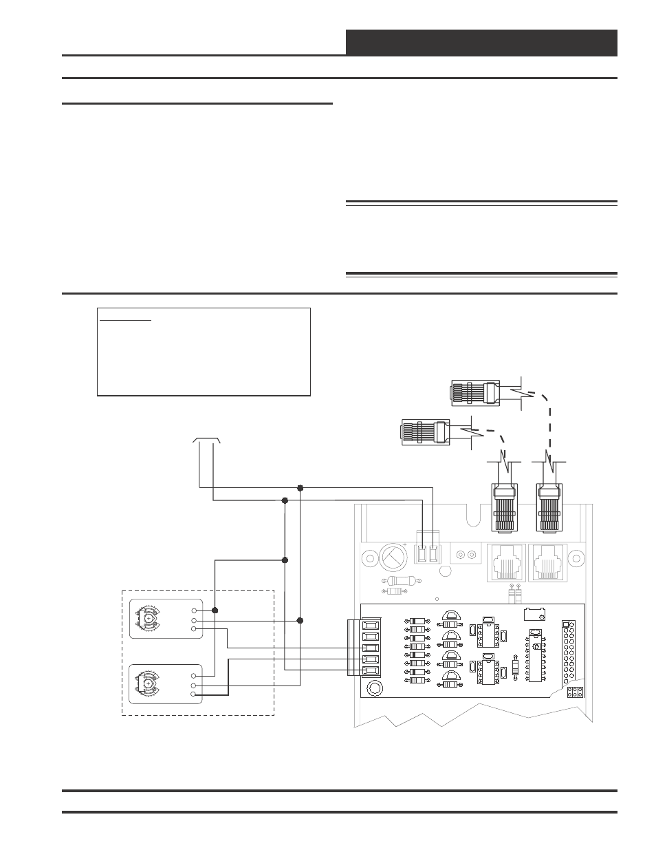
Return Air Bypass Wiring
The VCM controller can be configured for PAC or DPAC control
schemes. Both PAC and DPAC control schemes provide improved mois-
ture removal capabilities while utilizing internal space loads for reheat
by redirecting the Return Air around the Evaporator Coil instead of
through the coil. See the PAC and DPAC applications section of this
manual for complete operation details.
The PAC & DPAC control schemes both utilize a Return Air Bypass
Damper Actuator and a Return Air Damper Actuator to modulate the
Return Air and Return Air Bypass Dampers to control the amount of
air that is redirected around the Evaporator Coil.
The DPAC control scheme provides improved moisture removal ca-
pabilities and tighter temperature control than the PAC controls scheme
by combining Digital Compressor control in addition to Return Air
Bypass control.
See Figure 28 for detailed wiring of the Return Air Bypass and Return
Air Damper Actuators.
See Figure 16 for detailed wiring of the Digital Compressor.
Warning: It is very important to be certain that all wiring is
correct as shown in the wiring diagram below.
Failure to observe the correct polarity could
result in damage to the Damper Actuators or the
Analog Output expansion board.
Figure 28: Return Air Bypass Wiring
24
V
A
C
GND
10 VA Minimum Power Required For
Each 2 Slot Expansion Base Board.
20 VA Minimum Power Required For
Each 4 Slot Expansion Base Board
R20
C8
TB2
D3
PWR LD1
24V
AC-IN
GND
GND
TB1
PJ2
+24VDC-OUT
R17
PJ1
R15
Connect To VCM Controller
Connect To Next Expansion Board
(When Used)
GND
AOUT4
AOUT3
0-10 VDC
0-10 VDC
GND
OE355
-
4
Analog
Output
Board
OE352 or OE353 Expansion Base Board
WARNING!!
Observe Polarity! All boards must be wired with GND-to-
GND and 24VAC-to-24VAC. Failure to observe polarity will
result in damage to one or more of the boards. Expansion
Boards must be wired in such a way that power to both the
expansion boards and the controller are always powered
together. Loss of power to the expansion board will cause
the controller to become inoperative until power is restored
to the expansion board.
GND
AOUT1
YS101786
4 AOUT MOD. I/O BD.
CX1
U1
Q1
LM358
R2
U2
R9
D1
R6
D2
R7
D4
D3
R8
TB1
CX2
C3
C1
P1
RV
1
R1
C4
U3
C2
LM358
CX3
AOUT2
AOUT3
AOUT4
Q2
R3
Q4
Q3
R4
R5
Return Air Bypass
Damper Actuator
(0-10 VDC)
Return Air
Damper Actuator
(0-10 VDC)
Belimo Actuator Wiring
Shown. Consult Factory For
Other Manufacturers Wiring
Instructions
Y1
3
Y1
3
+
2
+
2
COM 1
COM 1