Figure 26: modulating heating device wiring, Warning – Orion System VCM Controller User Manual
Page 29
VCM Controller
Technical Guide
29
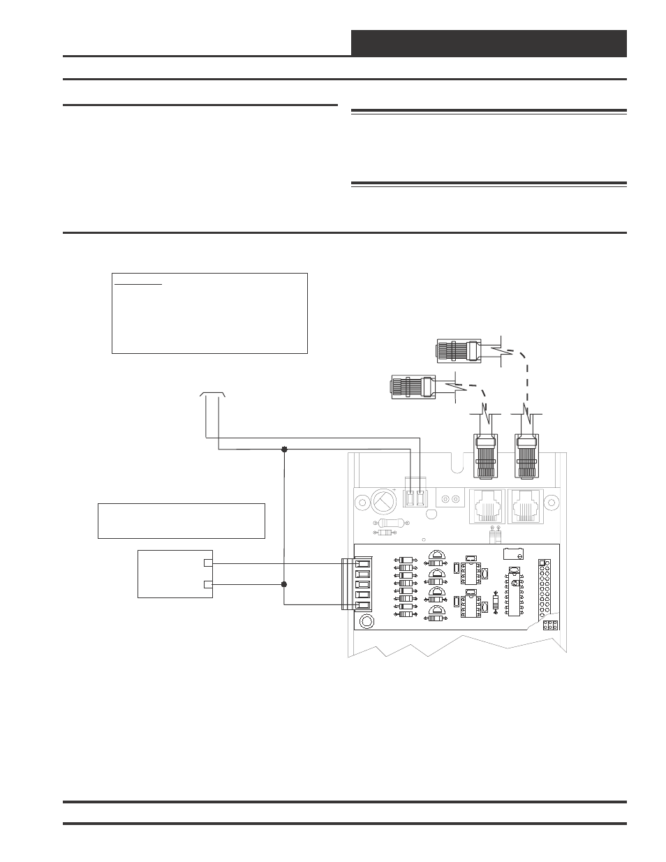
Modulating Heating Device Wiring
The Modulating Heating Device signal can be configured for either a
0-10 VDC or 2-10 VDC output signal. The output signal can be config-
ured for either Direct Acting or Reverse Acting operation as required.
The Output signal is normally used to control a Modulating Hot Water
Valve, Modulating Steam Valve or for SCR Control of an Electric Heat-
ing Coil.
See Figure 26 for detailed wiring of the Modulating Heating Device.
24
V
A
C
GND
10 VA Minimum Power Required For
Each 2 Slot Expansion Base Board.
20 VA Minimum Power Required For
Each 4 Slot Expansion Base Board
R20
C8
TB2
D3
PWR LD1
24V
AC-IN
GND
GND
TB1
PJ2
+24VDC-OUT
R17
PJ1
R15
Connect To VCM Controller
Connect To Next Expansion Board
(When Used)
GND
AOUT1
+
Modulating Heating Device
(By Others)
_
0-10 VDC or 2-10 VDC
(Configurable)
GND
The Modulating Heating Device Used Must Be Designed To
Accept Either a 0-10 Or a 2-10 VDC Input. The AOUT1
Output Voltage Is User Configurable For Either Voltage. The
Heating Device Used Can Be A Modulating Hot Water Valve,
Steam Valve Or SCR Controlled Electric Heating Coil.
OE355
-
4
Analog
Output
Board
OE352 or OE353 Expansion Base Board
WARNING!!
Observe Polarity! All boards must be wired with GND-to-
GND and 24VAC-to-24VAC. Failure to observe polarity will
result in damage to one or more of the boards. Expansion
Boards must be wired in such a way that power to both the
expansion boards and the controller are always powered
together. Loss of power to the expansion board will cause
the controller to become inoperative until power is restored
to the expansion board.
GND
AOUT1
YS101786
4 AOUT MOD. I/O BD.
CX1
U1
Q1
LM358
R2
U2
R9
D1
R6
D2
R7
D4
D3
R8
TB1
CX2
C3
C1
P1
RV
1
R1
C4
U3
C2
LM358
CX3
AOUT2
AOUT3
AOUT4
Q2
R3
Q4
Q3
R4
R5
Warning: It is very important to be certain that all wiring is
correct as shown in the wiring diagram below.
Failure to observe the correct polarity could
result in damage to the Modulating Heating Device
or the Analog Output expansion board.
Figure 26: Modulating Heating Device Wiring